ESP32-S3 Edge DTU Development | Obeita
This configuration is proposed for assessment. Confirm interfaces, components and performance for your specific project.
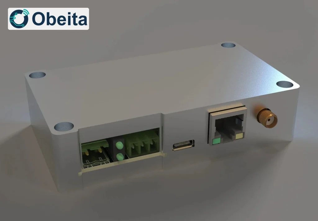
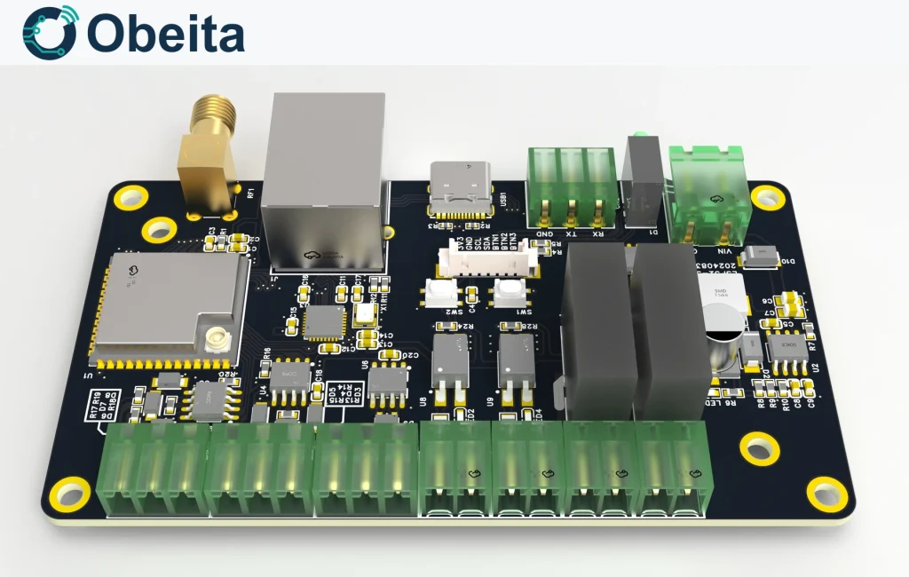
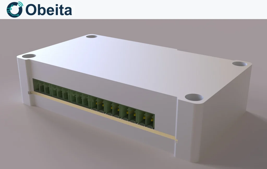
Bring serial devices, contact signals and a CAN interface onto one ESP32-S3 edge board. This 24 V design combines two RS485 channels, a TTL port, isolated inputs and relay outputs with Wi-Fi or 10/100 Ethernet, making it a practical starting point for a small machine data-and-control gateway.
Field interfaces beyond a serial converter
Two RS485 channels and one TTL channel serve serial equipment, while two PC817 optocoupler inputs read discrete states. Two HF46F-024-HS1 relays are driven by ULN2003 circuitry. The CAN transceiver adds a separate physical bus; CAN application protocol support must be included explicitly in firmware scope.
Networking and local configuration
The ESP32-S3-WROOM-1U provides Wi-Fi, and a CH390 SPI Ethernet controller provides the wired path. RS485/TTL-to-TCP forwarding is the base software direction. A USB command-line terminal can expose configuration settings during commissioning. Local processing, cloud payloads and additional control logic are extensions rather than implied functions of every connector.
24 V cabinet integration
SGM6232 converts the 24 V rail to 3.3 V. TVS components are included on RS485, CAN and power paths, but final immunity levels require product tests. Data connectors use a 3.81 mm pitch and power connectors use 5.08 mm. A printed enclosure and an added rail bracket can be adapted for cabinet mounting; relay coil voltage and enclosure clearances must remain consistent with the power design.
Proposed design configuration
These are configuration inputs for development; the final assembly, firmware and acceptance tests define the delivered specification.
| Item | Configuration |
|---|---|
| Main module | ESP32-S3-WROOM-1U |
| Network controller | CH390, 10/100 Ethernet; Wi-Fi |
| Serial buses | 2 × RS485; 1 × TTL |
| CAN | 1 × SIT65HVD232DR transceiver path |
| Discrete I/O | 2 optocoupler inputs; 2 relay outputs |
| Supply design | 24 V DC; SGM6232 conversion |
Project questions
Can a 12 V relay replace the 24 V relay directly?
Not without reviewing coil supply, drive current and the output circuit. The base design uses a 24 V coil; changing it is a hardware revision.
Is CAN ready for any industrial protocol?
The transceiver provides the electrical interface. CAN identifiers, bit rate, frame decoding and any higher-level protocol still need a defined implementation.
Plan this project
Send the two RS485 device manuals, CAN protocol, input signal type and relay loads, together with the available cabinet supply.