Modbus Remote I/O Integration | Obeita
This configuration is proposed for assessment. Confirm interfaces, components and performance for your specific project.
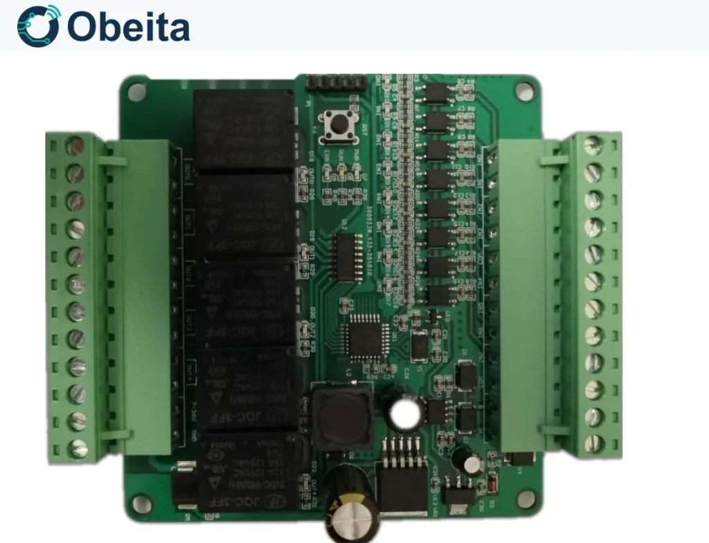
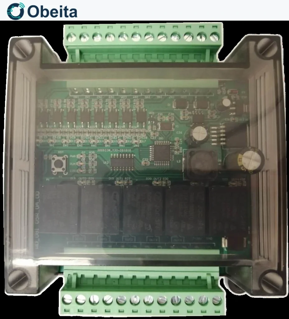
Extend a controller with eight dry-contact inputs and five relay outputs on an RS485 Modbus RTU bus. This I/O design separates remote command control from local input-to-output linking, so the same hardware can serve monitored contacts or a small local switching panel.
Remote control versus local interlocking
In remote mode, input readings and output commands are independent. In local mode, IN0–IN4 are associated with OUT0–OUT4 and remote output commands do not own those channels. Maintained-contact mode follows the contact state; momentary-contact mode toggles the state on a closure. These behaviours should be agreed before integrating a PLC or supervisory application.
Register map for software integration
The design map allocates 0x0000–0x0007 to inputs and 0x1000–0x1004 to outputs. Configuration starts at 0x2000: device address, baud selection, control mode and input mode occupy 0x2000–0x2003. Model information starts at 0x6000 and software version is at 0x6008. The final protocol document must also specify Modbus function codes, access permissions and zero-based addressing.
Rail mounting and load selection
The enclosure direction is 95 × 90 × 40 mm with a 35 mm DIN-rail slot and a 7–36 V supply design. Relay switching must be matched to resistive, inductive or high-inrush loads. A nominal relay marking is not a universal load allowance. The address range is also normalised to standard Modbus unicast practice: 1–247, with address 0 reserved for broadcast where applicable.
Proposed design configuration
These are configuration inputs for development; the final assembly, firmware and acceptance tests define the delivered specification.
| Item | Configuration |
|---|---|
| Inputs | 8 dry-contact channels; IN0–IN7 |
| Outputs | 5 relay channels; OUT0–OUT4 |
| Bus | RS485 / Modbus RTU |
| Baud selections | 9600 / 19200 / 38400 / 57600 / 115200; lower rates require firmware check |
| Control modes | Remote independent control / local linking |
| Mechanical design | 95 × 90 × 40 mm; 35 mm DIN rail |
Project questions
Why might a remote write not change a relay?
Check control mode first. In local mode, the associated input owns the output. Then verify function code, addressing and whether the channel permits writes.
Can station addresses 248–255 be used as normal Modbus slaves?
They are not part of the standard 1–247 unicast range. The firmware configuration should reject reserved addresses unless a separately documented proprietary mode is intended.
Plan this project
Send the contact types, relay loads, intended control mode and PLC register conventions for an I/O mapping review.