Sensor Timestamps: Distinguish Conversion Time from Interrupt and Readout Time
A sensor timestamp is meaningful only when it names the event being timed. Conversion start, conversion completion, interrupt handling, bus-read completion, and userspace receipt can all occur at different instants. Establish the physical sampling event first, then trace how the driver attaches a clock reading to that sample.
Applicability: the concrete converter reference is Analog Devices AD7606/AD7606-6/AD7606-4 Rev. G. The software reference is the Linux v6.12 IIO triggered-buffer framework. The illustrated software path is a proposed integration model, not a claim about the AD7606 driver’s implementation. Oversampling is excluded from the simple single-edge sampling example.
1. Name the physical event
The AD7606 datasheet’s conversion-control section states that tying CONVST A and CONVST B together allows the common rising edge to initiate simultaneous sampling across all channels. BUSY then indicates conversion activity, and its falling edge announces that the new result is available to read.
Those are distinct events. A timestamp associated with BUSY falling describes result availability unless the system explicitly derives a sampling-time estimate from it. A timestamp taken after the serial read describes an even later software observation.
Check mode changes before assigning one epoch to an entire scan. Independently driven CONVST inputs can give channel groups different sampling instants. With oversampling enabled, the result combines multiple internally timed samples. A single-edge label then needs a documented convention such as the beginning or representative time of an observation window.
2. Trace the software capture point
The IIO triggered-buffer guide describes a common arrangement: a short top-half poll function records time, while a threaded bottom half reads data and pushes it with that saved timestamp. This can avoid adding the entire bus-read delay to the timestamp, but the meaning still depends on what triggered the poll function.
The v6.12 implementation of iio_pollfunc_store_time() reads the IIO device clock when that function runs. It does not inherently recover the hardware sampling edge. Interrupt delivery and any earlier trigger-handling work have already occurred.
Inspect the deployed driver, trigger source, and buffer-push call together. Follow the exact variable passed as the timestamp. A variable named sample_time may contain a late clock read; a correctly captured early timestamp may be accidentally replaced at publication. Record the code location and release in the interface contract.
3. Build an event-to-timestamp ledger
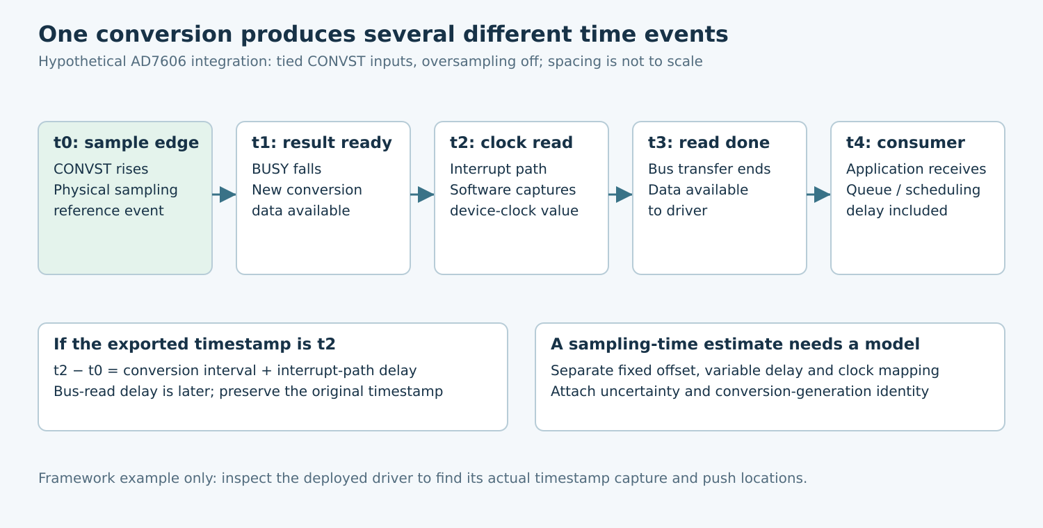
For a hypothetical AD7606 integration with tied CONVST inputs and no oversampling, name five instants: t0 is the common sampling edge; t1 is BUSY falling; t2 is the interrupt-path clock read; t3 is completion of the data transfer; and t4 is delivery to the consuming application.
Associate each timestamp field with exactly one of these events. If the exported timestamp is captured at t2, do not label it t0 merely because the same buffer contains the conversion result. If an application also records t4, preserve it as receipt time rather than overwriting the original field.
Record which conversion generation the data belongs to. A correctly measured t2 attached to a previous conversion is still wrong. Check result-register update rules, missed edges, read failures, and queue overflow. Sequence tracking or explicit gap indicators should make a missing sample visible rather than allowing the next successful read to inherit an old timestamp.
4. Separate offset, variation, and clock uncertainty
For a timestamp captured at t2, the difference from t0 contains at least the conversion interval and the delay from hardware completion to the software clock read. A later timestamp at t3 also includes data-transfer and scheduling delays. Write these terms separately so changing bus speed cannot silently alter the claimed sampling epoch.
Classify each term as specified by the device, bounded by measurement, estimated statistically, or unknown. Subtracting an average delay can remove an average offset; it does not remove sample-to-sample variation or establish a worst-case bound. Report the residual uncertainty using the same assumptions as the correction.
Clock mapping is another term. The Linux timekeeping documentation distinguishes clocks with different adjustment and suspend behavior. Verify the IIO device’s selected clock and the clock used by any external capture hardware. A high-resolution integer is not evidence that two clock domains are synchronized.
For cross-sensor alignment, define the required relative timing error and identify the common event or clock relationship that supports it. Two timestamps both expressed in nanoseconds may refer to unrelated epochs or different capture locations. Resolve those semantics before comparing numerical differences.
5. Measure the event chain under controlled load
- Capture physical markers: observe CONVST, BUSY, and the relevant bus activity using appropriate instrumentation and loading.
- Locate software timing: correlate a trace event or carefully characterized diagnostic marker with the clock-read location. Include instrumentation overhead in the interpretation.
- Preserve sample identity: connect each raw result to its trigger generation and software record. Do not align streams solely by arrival order after a loss.
- Vary workload: compare quiet operation with representative interrupt, CPU, and bus contention. Keep converter mode and sampling cadence fixed.
- Vary readout separately: change bus speed or consumer scheduling within supported limits. A preserved early timestamp should retain its capture semantics even when delivery becomes later.
Save distributions and worst observed delays with workload and capture conditions. A finite test’s largest delay is an observed maximum, not automatically a guaranteed bound. If the application requires a tighter bound than software capture can establish, investigate a supported hardware capture or shared-trigger design and qualify that path independently.
6. Publish a timestamp contract
The contract should state physical event, converter mode, channel grouping, capture location, clock domain and units, any correction model, uncertainty basis, and behavior after missed samples or configuration changes. Include separate availability or receipt timestamps when consumers need latency information.
No AD7606 timing capture or Linux driver execution was performed for this article. The proposed event ledger and load tests are the engineering deliverable. Acceptance requires evidence that every exported timestamp refers to the intended conversion generation and that any sampling-time claim carries a defensible relationship to the physical acquisition event.