Bluetooth Direction Finding: Separate IQ Capture Quality from Position Estimates
Validate the IQ acquisition record before evaluating an angle estimator. Confirm the CTE type, sample format, packet status, reference-sample boundary and physical antenna sequence. Then verify the coordinate transform separately. A plausible angle can survive several mapping errors while pointing in the wrong direction.
Applicability: Bluetooth Core 6.1 connectionless CTE IQ reports and Zephyr v4.2.0 Direction Finding interfaces. The proposed fixture uses AoA with a supported two-microsecond switching/sampling configuration. Timing values describe the protocol; no radio GPIO assignment, antenna-switch settling time or board accuracy is specified. Hardware configuration requires the exact selected radio, switch and board documentation.
1. State which end switches antennas
For AoA, the transmitter holds its antenna while the receiver switches. For AoD, switching happens at the transmitter and the receiver need not switch. These are distinct Core CTE arrangements, so a receiver-side pattern copied between the modes is not automatically meaningful.
Save transmitter and receiver firmware identities, CTE type, supported slot duration, array revision and selected pattern. Separate the software antenna identifier from the physical element and its position. An accepted configuration does not prove that a control line reaches the intended RF switch input.
Create an antenna mapping worksheet with logical ID, controller pattern value, board control connection, switch state and physical element coordinates. Verify it using the selected manufacturers’ documents and the actual board. Leave an unverified row unresolved rather than borrowing another development board’s pinout.
2. Count reference and switched samples separately
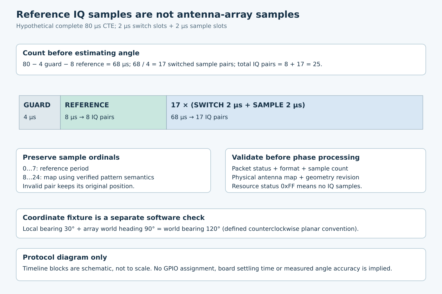
The Core structure has a four-microsecond guard, an eight-microsecond reference period and alternating switch/sample slots. Reference sampling produces eight IQ pairs. In the proposed two-microsecond configuration, each following switch-plus-sample pair occupies four microseconds.
For a hypothetical complete 80-microsecond CTE, the post-reference duration is 80−4−8=68 microseconds. That contains 17 switch/sample pairs, making 8+17=25 IQ pairs in the report. The first eight pairs are reference observations, not eight different antenna elements.
This count is a fixture expectation for the stated complete capture. Resource limitations and invalid samples require their own outcomes. Do not force every arriving array to length 25 by padding zeros, because a fabricated complex sample can influence phase and amplitude processing.
Keep sample ordinal, period kind and expected antenna identity together. Derive the post-reference mapping from the documented controller pattern semantics. Do not assume that the first array element corresponds to the first antenna in a repeating switching list.
3. Decode status and format before phase
The HCI Connectionless IQ Report carries packet status, channel, CTE type, slot duration, periodic event counter and samples. A resource-shortage report has status 0xFF and zero samples; channel, CTE type and slot duration are invalid in that case.
For the standard eight-bit sample representation, 0x80 marks an unavailable I or Q sample, and both components must agree on availability. Preserve its ordinal as an invalid pair. Removing it and shifting all later samples would corrupt the antenna mapping.
The Zephyr v4.2.0 report identifies eight-bit standard samples separately from a vendor-specific sixteen-bit extension. Select the correct union member and decoder from sample_type. Do not apply the eight-bit sentinel or scaling assumptions to a sixteen-bit vendor format without that format’s documented contract.
For an initial conservative qualification policy, accept only CRC-correct packets for estimation and retain other reports diagnostically. The controller can report some bad-CRC observations, but accepting them is an explicit estimator policy requiring evidence, not a reason to erase packet status.
Use separate counters for received reports, resource failures, malformed records, invalid sample pairs and estimator rejections. A zero-sample resource report indicates an acquisition problem; it is not an angle of zero degrees and not proof that the beacon disappeared.
4. Define a complete estimator input record
| Input group | Retain |
|---|---|
| Observation identity | Sync generation, event counter, arrival time and observation timing if exposed |
| Radio context | Channel, CTE type, slot duration and packet status |
| Sample representation | Width, signed interpretation, scaling and validity mask |
| Array context | Pattern revision, ordinal-to-element mapping and geometry |
| Estimator context | Algorithm, calibration and coordinate-frame revisions |
Keep frequency-offset treatment and reference-period processing explicit in the estimator configuration. An unexplained phase trend across reference samples should be investigated before interpreting switched-sample phase differences as spatial information.
Record channel-dependent and element-dependent calibration under named revisions. Avoid fitting a correction to one favorable orientation and calling the array calibrated. Preserve raw captures so a decoder or calibration change can be evaluated against identical observations.
Bound capture storage and processing latency. If the application drops a report, count that as a host-side loss. Do not attribute every missing estimate to radio reception or hide queue delay inside the angle estimator’s timing.
5. Test the coordinate frame without a radio
Define array origin, axes, handedness, positive angle direction and angle wrapping. State whether the estimator produces azimuth only or a fuller directional result. A direction vector does not determine a unique three-dimensional position without additional geometry or observations.
For a hypothetical planar fixture, let local +x define zero degrees and positive angles run counterclockwise. Mount the array with its local +x at world heading 90 degrees. A local bearing of 30 degrees then maps to world bearing 120 degrees under that convention.
Test zero, positive, negative and wrap-boundary bearings through the transform. Deliberately reverse two antenna identities and confirm that the mapping validation detects the inconsistent revision rather than allowing a visually plausible but mirrored result.
These are deterministic software checks, proposed here rather than executed. They validate coordinate interpretation; they do not measure the array’s angular error or resolve an estimator’s physical ambiguities.
6. Qualify acquisition and angle accuracy in stages
First replay a complete 25-pair fixture, an invalid pair in the switched portion, a resource-shortage report and the wrong sample format. Confirm preserved ordinals, explicit rejection and correct decoder selection.
Then use a controlled transmitter and known physical orientation to inspect actual pattern operation and capture consistency. Vary channel, angle, obstruction and the supported environment while retaining a reference condition. Report valid-capture fraction separately from angular error among accepted estimates.
Release the estimator only with a traceable acquisition contract and an explicit local-to-world transform. A clean IQ buffer, an accepted angle and a useful position are three separate outcomes; each needs its own evidence.