STM32WB Antenna Reuse: Requalify the Board Geometry Behind the Reference Match
Copying a reference antenna's component values onto a smaller STM32WB board does not preserve the electrical environment in which those values were selected. The reference ground plane and nearby board structures participate in the antenna system. Changing them can invalidate the reference match even when the antenna part number stays the same.
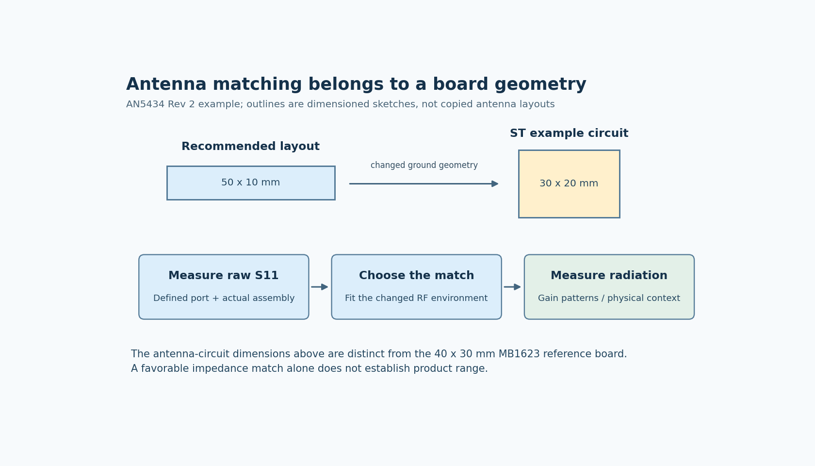
The worked hardware evidence here is a WB reference environment, even though AN5434 covers WB and WBA antenna design more broadly. ST's AN5434 Rev 2 provides a concrete example: a chip antenna's recommended 10 by 50 mm layout was replaced with a 20 by 30 mm circuit to fit the reference-board arrangement. The resulting ground-plane difference required different matching components. That is a useful warning against treating the matching network as a portable bill-of-materials fragment.
Identify what the reference actually measured
AN5434, Guidelines for on-board antenna reference designs, evaluates antennas with the MB1623 board, which is 40 mm high and 30 mm wide. Its introduction to the board explains that proximity and orientation affect radiation behavior. The note also compares simplified and more complete models, including nearby structures such as the battery and USB connector.
Section 6.4's TDK ANT016008LCS2442MA2 example does not preserve the antenna manufacturer's recommended board geometry. ST first measures the unmatched reflection coefficient on its changed circuit, uses that result to choose the match, and then measures gain patterns. The sequence is important: the changed structure is characterized before its reference component values are accepted.
For a new product, distinguish the antenna element, the antenna circuit's ground geometry, and the rest of the product PCB. The 10-by-50 and 20-by-30 dimensions in this example describe the compared antenna layouts; they are not alternative dimensions for the entire 40-by-30 MB1623 board.
Turn reuse into a set of explicit assumptions
Start the layout review by placing the reference and proposed design side by side. Mark the antenna position, ground boundaries, feed route, matching footprint and adjacent conductors. Record changes in board dimensions and the placement of batteries, connectors or other substantial structures near the antenna.
This comparison is not a claim that every difference is harmful. It identifies which conditions were changed, so that a successful reference measurement is not silently attributed to a different assembly. A smaller outline can alter the ground structure even if the antenna corner is copied exactly. Conversely, preserving total board area would not establish the same shape or current paths.
Keep tuning provisions accessible on the prototype. The reference match is a starting configuration to investigate, not evidence that those values are final. The article's engineering proposal is to qualify the actual product geometry before freezing the matching components and enclosure arrangement.
Separate an impedance result from a radiation result
An S11 measurement describes reflection at a defined measurement port. It does not by itself establish the product's useful radiation pattern or application range. A favorable match therefore answers only part of the reuse question.
Follow the distinction visible in ST's own sequence. First establish the measurement reference plane and characterize the changed antenna assembly. Tune the match over the required operating band. Then assess radiation behavior with the board in the intended physical arrangement and relevant orientations. Avoid turning a single-frequency impedance minimum into a claim about all channels or all directions.
AN5434's plots belong to its documented prototypes and test conditions. Do not copy their gain or efficiency numbers into a product estimate merely because the new PCB uses the same antenna family. The note even discusses measurement differences associated with its added coaxial connection and substrate-permittivity changes, illustrating why the fixture and construction need to remain part of the record.
Keep radio bring-up and antenna qualification connected
The STM32WB bring-up procedure, AN5378 Rev 3, distinguishes conducted RF access from the PCB-antenna route. Its MB1355C example changes populated routing components when selecting the SMA path. Those component designators belong to that board revision; they are not instructions for a WBA custom board.
The transferable decision is to know which path a measurement exercises. A conducted test can help isolate radio or feed-path problems, but does not validate the final antenna's radiation. An over-the-air failure can involve both the radio chain and the antenna assembly. Providing a deliberate, documented test-access arrangement helps separate those possibilities without assuming that the production antenna is already qualified.
A reuse decision is ready when the changed geometry is documented, the selected match is supported by measurements of that assembly, and radiation results address the product's physical use. No measurements or RF qualification were performed here. The source-backed conclusion is narrower: reference antenna values are conditional on their board environment, and ST's own changed-ground-plane example demonstrates why that condition must be revisited.