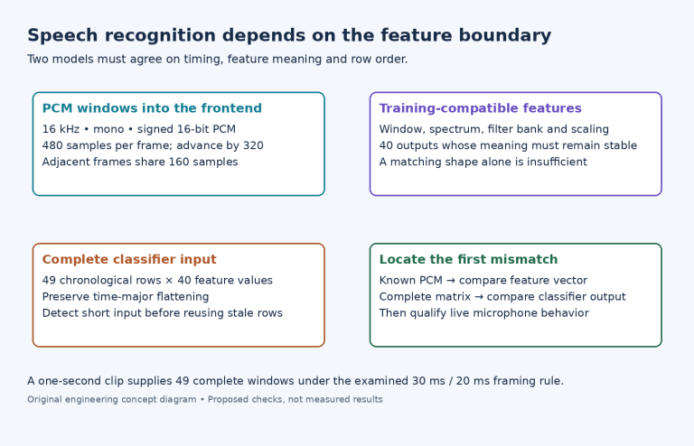
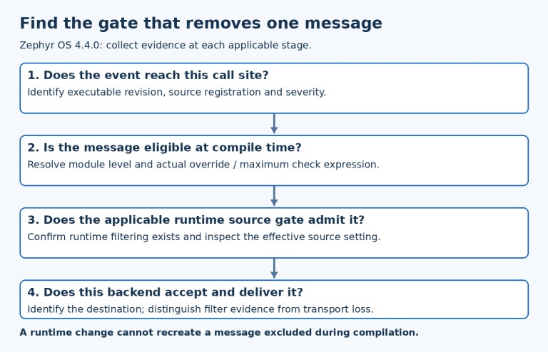
STM32G474 PWM Dithering: Measure the 16-Cycle Average Without Promising Finer Individual Edges
STM32G474 timer dithering improves the average PWM setting across a sixteen-period pattern. It does not move each individual edge to a fractional timer-clock position. A scope that displays only one cycle can therefore show two integer pulse widths even when the average follows the requested fractional compare value.
The example uses TIM1, edge-aligned up-counting PWM with a fixed integral period and an active-high output. RM0440 Rev 9, section 29.3.13, pages 1181–1184 defines the encoding and pattern. This is arithmetic for an inert waveform fixture; no load, converter or motor performance was measured.
Decode the fractional field once
With TIM1_CR1.DITHEN enabled, bits 19:4 carry the integer part of the affected ARR and CCR values, and bits 3:0 carry the sixteenths component. For a compare setting of twenty plus six sixteenths:
encoded CCR1 = (20 << 4) | 6 = 326 = 0x146
average compare count = 20 + 6 / 16 = 20.375
Choose a one-hundred-count period for this example. In the stated edge-aligned up-counting mode, the integer auto-reload value is 99, so the dithered encoding with no fractional period component is 99 << 4, or 0x630. Keeping the period integral isolates compare dithering from frequency dithering.
The manual says changing DITHEN automatically converts the existing ARR and CCR encoding. For example, enabling it changes an existing integer value five to encoded value 0x50. Code that then shifts that already-converted register again multiplies the intended base by sixteen a second time.
Keep desired logical counts separate from encoded register values. A configuration function should know which representation its argument contains. Reading a register back and passing it through an integer-to-dither conversion helper is unsafe unless the helper’s contract explicitly expects that representation.
Count the six longer pulses
For fractional field 0b0110, Table 273 adds one timer count in periods 1, 3, 5, 9, 11 and 13 of its documented pattern. The other ten periods retain the base compare count. The constructed width list is:
21 20 21 20 21 20 20 20 21 20 21 20 21 20 20 20The sum is 6 * 21 + 10 * 20 = 326 active counts over sixteen periods. Dividing by sixteen gives 20.375 active counts per period. With the fixed one-hundred-count period, the average duty ratio is 20.375 percent.
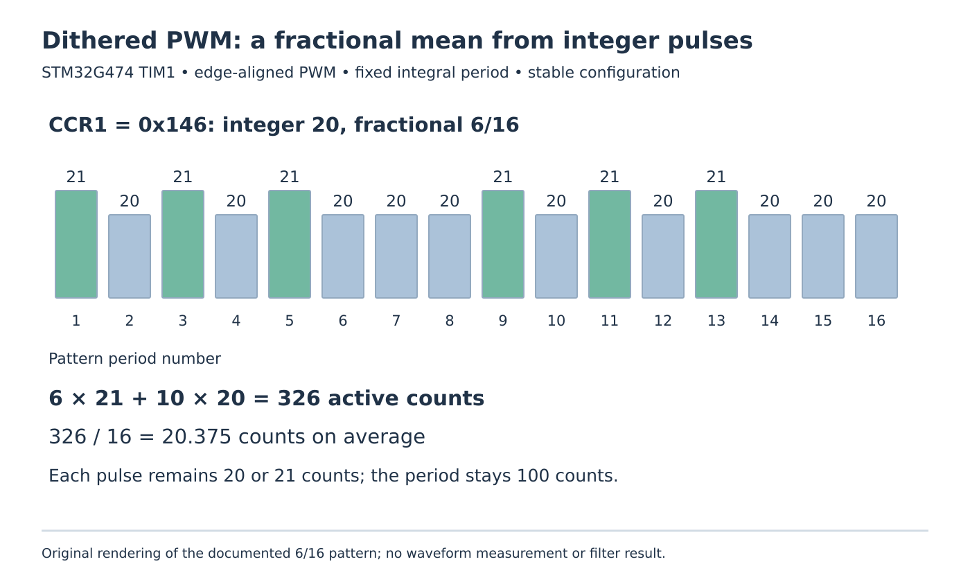
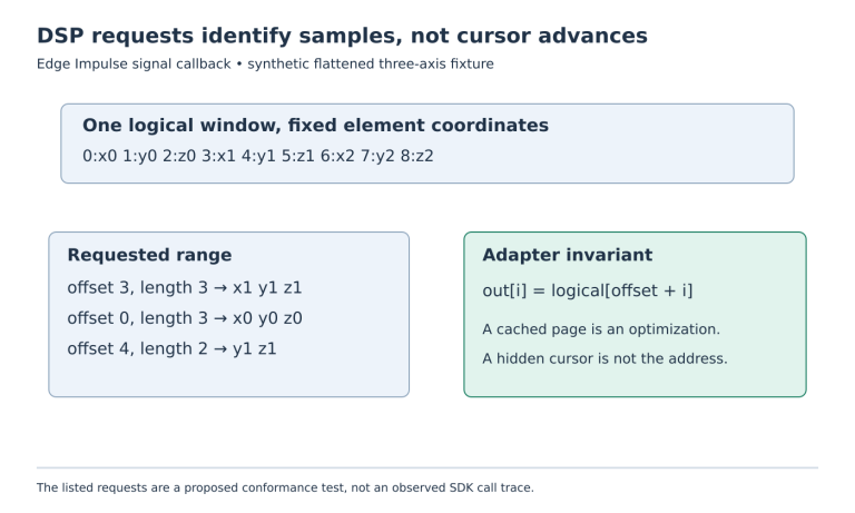
Individual pulses still occupy either twenty or twenty-one timer counts. The fractional average is a property of the sequence. A consumer that requires every edge at exactly 20.375 counts cannot satisfy that requirement through this mechanism.
Similarly, the duty-cycle arithmetic says nothing about analog ripple after a filter. Filter response, load behavior and clock uncertainty would need their own model and measurements. Describing the average with extra digits does not certify an improved physical output.
Observe an entire stable pattern
For a proposed isolated logic-level test, hold the configuration steady and capture at least a complete sixteen-cycle pattern. Count longer pulses and sum active times rather than selecting whichever cycle looks closest to the requested mean. If acquisition begins partway through the pattern, preserve that phase context instead of falsely labeling the first captured cycle as hardware pattern period one.
Check period constancy separately. An unintended nonzero fractional field in ARR would mix period variation into a test intended to examine compare variation alone. Retain raw register values and their decoded integer/fractional parts with the capture.
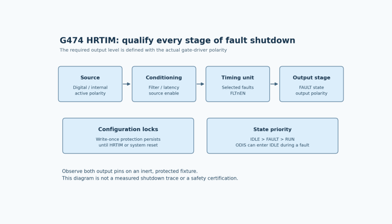
Changing or disabling dithering also needs the documented transition procedure. RM0440 specifies stopping the counter and clearing ARPE, clearing ARR[3:0], resetting DITHEN, then clearing compare flags before restart. This article does not prescribe a live transition on an operating power stage.
Preserve the center-aligned erratum boundary
ES0430 Rev 9, section 2.12.3 describes missed compare events with dithering in center-aligned modes 1 and 2 at specified extreme compare values. The matrix marks revisions Z, Y and X affected without a workaround. The text distinguishes incorrect toggle output from other output modes and exempts center-aligned mode 3.
Do not broaden that limitation into a claim that every dithered PWM waveform fails. Equally, a visually correct PWM output does not prove an affected compare interrupt was generated. The main edge-aligned fixture avoids that specific condition; a different mode needs its own review.
Acceptance for this example is precise: the decoded setting is twenty plus six sixteenths, the stable pattern has six longer pulses, and the sixteen-cycle aggregate matches 326 active counts. No fractional individual edge or application-level improvement is claimed.