STM32F401CCU6 USB Device FIFOs: Fit Payload and Status Words into the Dedicated RAM
A composite USB device can have a plausible endpoint list and ample free application SRAM yet still have an invalid FIFO map. STM32F401CCU6’s OTG FS peripheral owns a separate, limited RAM block. Firmware partitions that block between receive storage and transmit FIFOs; extra CPU SRAM does not enlarge it.
This article pins RM0368 Rev 6, sections 22.10–22.13.1 and 22.16.2 for OTG FS in device mode. The documented dedicated capacity is 1,280 bytes, or 1280 / 4 = 320 32-bit words. Host-mode allocation formulas and other STM32 families are outside this budget.
Build the active endpoint inventory first
For each endpoint in the active configuration, record direction, transfer type and maximum packet size. Include control endpoint zero in both the receive and transmit review. Endpoint-address validity, supported transfer types and USB class requirements remain prerequisites; a memory spreadsheet cannot establish those capabilities.
Figure 248 shows one shared receive FIFO for all OUT endpoints. Each active IN endpoint has a dedicated transmit FIFO. OUT payload and receive-status information therefore compete within one shared allocation, while separate IN allocations consume the same physical RAM block.
Do not equate an endpoint’s packet size with the entire receive requirement. The hardware also needs storage for control traffic and bookkeeping that is absent from the application payload.
Count receive overhead in words
Section 22.13.1 reserves ten receive locations for SETUP packets and one for Global OUT NAK. Each received packet needs payload storage plus a status word. Its discussion also recommends one completion-status location for each OUT endpoint.
For byte lengths that are not multiples of four, round payload storage upward. A hypothetical 63-byte payload occupies ceil(63 / 4) = 16 words, before its packet-status word. Dropping the fractional part would leave insufficient room for the final bytes.
The manual typically recommends two packet-and-status spaces so reception can overlap CPU removal. It specifically requires at least two such spaces when multiple isochronous endpoints are enabled. Keep that requirement separate from the general recommendation; neither establishes a universal optimum for every workload.
For a paper case with largest OUT packet size 64 bytes and two active OUT endpoints including endpoint zero, the recommended two-packet accounting becomes:
payload_words = ceil(64 / 4) = 16
RX ledger = 10 SETUP + 1 Global OUT NAK
          + 2 * (16 payload + 1 packet status)
          + 2 completion-status locations
          = 47 words
That is a source-derived budgeting example, not a validated endpoint composition or driver initialization value. A real configuration must also satisfy the selected field limits and its supported traffic requirements.
Check transmit minima and field limits separately
The device-mode allocation section requires each IN FIFO to hold at least that endpoint’s maximum packet. The register descriptions add a minimum depth of 16 words for the cited RX, endpoint-zero TX and other IN TX fields. A small interrupt-IN payload therefore does not justify a one-word FIFO merely because the bytes fit.
GRXFSIZ.RXFD and DIEPTXF0.TX0FD specify 256-word maxima as well. The other DIEPTXFx depth description must be read on its own terms; the total physical extent remains a separate limit regardless of what a field can encode.
Keep units explicit when translating the ledger into a chosen driver’s API. Packet sizes begin in bytes; these hardware FIFO depths are in 32-bit words. Reset-register values are not a ready-to-use initialized device map and must not be used to infer additional physical RAM.
Reject an oversized map before transfer testing
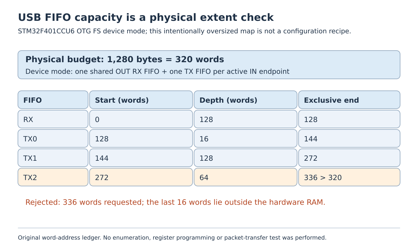
Consider this deliberately invalid, contiguous paper allocation. Ranges use word offsets and an exclusive end:
FIFO   start   depth   end
RX       0      128    128
TX0    128       16    144
TX1    144      128    272
TX2    272       64    336
The requested total is 128 + 16 + 128 + 64 = 336 words. It exceeds the 320-word capacity by 336 - 320 = 16 words, or 64 bytes. Nonoverlap among these four slices does not rescue the out-of-range final slice.
An arbitrary reduction is not yet a repair. Recompute the affected FIFO’s packet, status and minimum-depth obligations before choosing a smaller allocation. Conversely, a total below 320 does not rule out overlap if start addresses were programmed inconsistently. Check every start, depth and end against the same word-based address map, including the fixed receive start at zero.
Keep capacity separate from the FIFO-write erratum
ES0222 Rev 9, section 2.12.1 describes a device-mode corruption condition: endpoint-specific register accesses interrupting a transmit-FIFO write sequence can corrupt the next FIFO data written. Its workaround prevents that register-access interruption during the write sequence.
A capacity-correct map does not resolve that independent access-order constraint. Review the applicable silicon revision and driver path without importing the neighboring host-only receive-channel and transmit-FIFO workarounds into this device calculation.
No enumeration, controller programming, packet transfer or throughput test was performed. The deliverable is an endpoint-aware word ledger and a nonoverlapping physical map within the dedicated RAM. Subsequent qualification must separately establish endpoint activation, correct transferred bytes, supported traffic behavior and applicable erratum handling.