Bluetooth Mesh Models and Elements: Make Address Allocation Match the Physical Product
Start a Mesh product’s address plan with independently addressable behavior. Then map each physical function to an element, each element to its model instances, and each instance to the required keys and communication settings. A node address alone cannot identify every controllable output inside the enclosure.
Applicability: historical Bluetooth Mesh Protocol 1.1 elements, Composition Data and configuration states; Zephyr 4.2.0 declarations provide concrete model identifiers and configuration argument boundaries. The three-output fixture is hypothetical and omits unrelated mandatory product models for clarity. No actuator or mesh configuration was exercised.
1. Decide which functions need separate elements
Section 2.3.4 defines an element as an addressable entity. Message dispatch depends on opcode and element address. Overlapping instances that receive the same message in the same way cannot simply be placed together on one element and distinguished by an arbitrary application label.
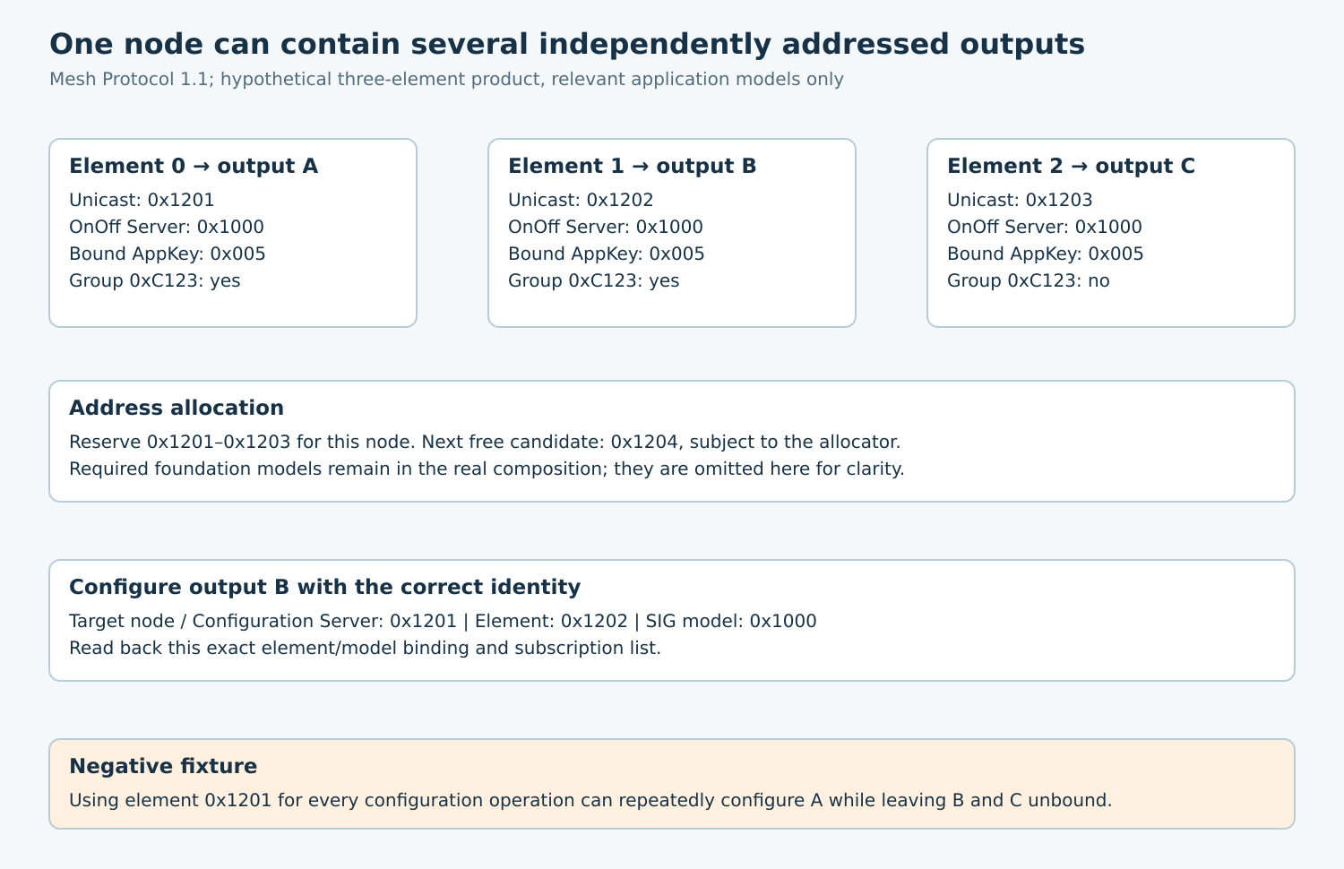
For three independently controlled on/off outputs A, B and C, use a separate element for each Generic OnOff Server instance. The Zephyr 4.2.0 access header identifies that SIG model as 0x1000. These instances share a model identifier but have different element addresses.
Multiple different models can belong to one element when their specified relationships permit it. Conversely, some model relationships span elements or share states. Consult the selected model specification rather than assuming one model always equals one physical component.
Keep the primary element’s required foundation functionality in the actual composition. The simplified output table is a mapping aid, not a complete compliant composition or a safety design for switching mains power.
2. Reserve the complete contiguous address range
The primary element uses the first assigned unicast address. Secondary elements use the subsequent addresses. In the hypothetical fixture, a primary address of 0x1201 and three elements reserve 0x1201 through 0x1203 inclusive.
| Element index | Unicast address | Physical function | Relevant model |
|---|---|---|---|
| 0, primary | 0x1201 | Output A | Generic OnOff Server 0x1000 |
| 1 | 0x1202 | Output B | Generic OnOff Server 0x1000 |
| 2 | 0x1203 | Output C | Generic OnOff Server 0x1000 |
The next nonoverlapping allocation could begin at 0x1204 if the allocator has no other reservation there. Provisioning another node at 0x1202 would collide with an element even though no second enclosure uses 0x1201.
Use the reported element count and a centralized allocation record. Validate address-range arithmetic and unicast bounds before committing provisioning data. Preserve reservations for uncertain provisioning outcomes instead of recycling them immediately.
3. Reconcile the map with Composition Data
Read Composition Data Page 0 after provisioning and compare the ordered element/model list with the supported product manifest. Page 0 carries element descriptions, SIG and vendor model lists, product identifiers and feature information.
Match a model instance by element address and model identity. A vendor model additionally needs its company identifier; do not treat its model number as globally equivalent to a SIG identifier.
Reject an unexpected composition before applying an old configuration script. A product variant with one fewer element can make “configure channel three” target the wrong place or fail ambiguously.
Mesh 1.1 makes Page 0 stable during a node’s term. Structural firmware changes require the specified term-changing procedures or lifecycle handling; they are not ordinary in-place array edits invisible to the Configuration Manager. Save the composition fingerprint and its qualified firmware context.
4. Keep three configuration relationships separate
An AppKey bound to a model permits the appropriate application-key use for that instance. A subscription selects multicast destinations the model receives. Publication defines how that model sends published messages. Adding a subscription does not install an AppKey, and installing an AppKey on the node does not automatically bind every application model.
For the fixture, bind AppKey index 0x005 to the OnOff Server on each intended element. Subscribe A and B to hypothetical dynamic group 0xC123, leaving C outside that group. Configure publication only where the product requires it.
Section 4.2.4 adds an important exception to independent subscription bookkeeping: models within an extension relation tree share a Subscription List per element. Inspect those relationships before assuming a subscription edit affects only the model named by the operator.
Keep publication address, AppKey index, period and other publication settings in their own record. A successful direct request/response does not establish that periodic or event-driven publication reaches the intended consumer.
5. Avoid the node-address versus element-address trap
The Zephyr configuration-client API makes the distinction explicit. bt_mesh_cfg_cli_mod_app_bind takes both the target node address and the element address containing the model, followed by AppKey index and model ID.
To bind output B in this fixture, the configuration request targets the node’s Configuration Server while identifying element 0x1202 and model 0x1000 in its payload. Reusing 0x1201 for every element argument can repeatedly configure A while leaving B and C unconfigured.
Check both the local function result and returned model status. The documented asynchronous form can return after sending without waiting for the remote response. Then query model AppKey and subscription lists for the same exact element/model identity.
Size readback arrays for the qualified configuration. The header documents caller-provided capacities for returned lists; a small local buffer must not become false evidence that no additional binding or subscription exists.
6. Prove physical mapping with negative cases
- Send a supported unicast control to each element in isolation: verify only its intended physical output changes.
- Send the group operation to 0xC123: verify A and B respond while C remains outside the group.
- Deliberately bind only element 0x1201 in a lab configuration: verify the checklist detects B and C’s missing bindings.
- Use a wrong AppKey or unbound model context: verify protected application behavior is not accepted.
- Restart the node and manager: verify persistent composition and configuration records still identify the same outputs.
- Present a changed or truncated composition: verify the configurator stops before applying stale element indices.
Separate network receipt, model state and physical output evidence. A returned status alone cannot reveal swapped GPIO wiring, while a toggled lamp alone cannot prove that the intended model and key were used.
The final deliverable is one reviewed mapping table plus readback and physical acceptance evidence. It should let a second engineer explain exactly why a message to an address affects one output, several subscribed outputs or none.