External Flash Deep Power-Down: Restore Storage Access Before the First Read
Gate the first storage read on the external flash’s actual exit-from-power-down sequence, not merely on the MCU’s wake event or the SPI controller becoming available. The device may still ignore ordinary commands while the software considers the system awake.
The concrete example here is Microchip SST25PF040C, datasheet DS20005397E, with a separate Zephyr v4.2.0 SPI-NOR driver review. This is a qualification method, not a claim that every board configuration supports that part. Commands, timing and state retention must be checked again for a substituted flash device.
1. Separate standby, deep power-down and power removal
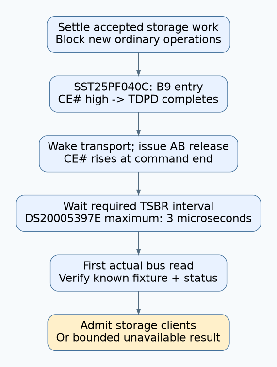
For this part, the datasheet’s section 5.13 specifies B9 for deep power-down entry and AB for release. Entry is ignored during an internal write operation. While in deep power-down, ordinary instructions are ignored except the documented release/Read-ID operation.
Figure 5-14 anchors the release interval to CE# returning high after the command. Table 6-8 lists a maximum TSBR of 3 microseconds; the entry interval TDPD is also listed as 3 microseconds. Those are part-specific limits, not total system wake time.
Removing supply power is a different transition. It needs the device’s power-up requirements and any lost configuration restored. Do not apply the deep-power-down interval to an actual power cycle, and do not infer retained state solely from the MCU’s reset reason.
| Observed transition | Question before the next read |
|---|---|
| Chip deselected but powered. | Is this ordinary standby, with no deep-power-down command? |
| Flash entered deep power-down. | Was release issued correctly, and did the CE#-anchored recovery interval elapse? |
| MCU reset while flash stayed powered. | Does startup account for a flash state inherited from the previous execution? |
| Flash supply removed. | Has the complete device-specific power-up and configuration path finished? |
2. Establish a storage admission barrier
Before entry, stop admitting new storage operations and settle the operations already accepted. A flash operation still busy at entry can make the intended power-down command ineffective. Record whether the implementation waited, rejected sleep, or followed another documented policy.
After wake, keep ordinary readers blocked until bus restoration, release-command completion and the required device interval have all finished. The barrier must cover every storage client, including diagnostics and a filesystem worker that can run before the main application resumes.
Assign one owner for the flash’s protocol transition. An application issuing raw release commands beside a power-managed driver can desynchronize the driver’s state or race its next suspend. Trace the existing owner before adding a second wake workaround.
3. Review the driver path and units
The Zephyr v4.2.0 SPI-NOR implementation distinguishes deep-power-down entry/exit, an alternate wake sequence, and device initialization. Its ordinary release path applies a configured exit delay after a successful command. Startup also attempts release before checking device readiness and identity.
The versioned SPI-NOR binding describes deep-power-down timing properties in nanoseconds. In this driver, the entry and exit values are rounded upward into milliseconds for the internal fields. A configured 3,000-nanosecond exit interval therefore becomes one millisecond in that path. This is a source-level conversion, not a measured wake latency.
Verify the generated configuration, selected wake path and actual driver revision. Do not copy a timing integer from a datasheet into a property without checking units. Also distinguish a configured wait from the waveform’s actual CE# transition; controller queuing can move the reference event.
4. Measure the command-to-first-read timeline
Use recoverable development hardware and non-sensitive fixture data already stored in a known region. Start with read-only wake tests. Capture CE#, clock, command bytes, driver transition markers and the first ordinary read. The diagram is a conceptual sequence; the test capture must establish actual timing.
- Confirm the device identity and the expected fixture bytes while fully awake.
- Enter deep power-down through the intended owner and record the completed entry transaction.
- Trigger the real wake path, including restoration of the SPI transport.
- Locate CE# rising at the end of the release command and measure to the first subsequent command.
- Verify the returned fixture content and read status, then repeat through representative sleep durations and supported operating conditions.
Do not let a filesystem or controller cache satisfy the test without accessing the flash. Prove that the first read reached the bus, or use a controlled uncached diagnostic path that does not change production security settings. An unchanged application value may be stale RAM data rather than evidence of a successful wake.
5. Interpret the failure signature
| Observation | Investigation |
|---|---|
| No release transaction before the first read. | Wrong driver path, missing configuration or a client bypassing the owner. |
| Release present; next command starts too early. | Delay reference, unit conversion, completion reporting or admission-barrier error. |
| Release timing correct; returned bytes wrong. | Bus mode, chip select, addressing, electrical conditions, device identity and actual supply history. |
| Only MCU-only reset fails. | Inherited flash state and differences between startup and ordinary resume. |
| Only quick sleep/wake cycles fail. | Entry completion and minimum timing assumptions at the transition boundary. |
An all-ones response is a symptom, not a unique proof of power-down. A wrong chip select, unresponsive device or electrical fault can produce similarly misleading data. Keep interpretation tied to the command capture and known fixture.
6. Add bounded failure handling
Set a product-level timeout for readiness and propagate a storage-unavailable result when it expires. Preserve the first failing stage. Repeated retries must not silently turn a first-read failure into a successful mount by discarding valuable data or automatically formatting a region.
Test a sleep request during an active read, a delayed release completion, an error returned by the SPI transfer, and a second sleep request during restoration. Any write/erase concurrency tests require a disposable region, preserved originals and explicit authorization for that test data to be destroyed.
Hypothetical first-read defect
A controller reads correct settings on its second attempt after wake. A trace shows that the first ordinary command begins before the release recovery interval finishes. The fix belongs in readiness sequencing and client admission, rather than adding a blind retry to every filesystem read.
Release with the exact part revision, generated driver configuration, command-to-read capture and bounded error path. No hardware timing, current saving or successful target test is claimed here; those remain the evidence the qualification plan must produce.