STM32WBA LE Audio Clocking: Keep the Codec Timer and Audio Peripheral on the Same PLL
Valid isochronous packets and completed LC3 decoding do not guarantee correctly timed audio output. In ST’s STM32WBA Codec Manager integration, the timer used to measure and schedule audio must share the PLL-derived clock used by the audio peripheral. Two nominally correct rates from unrelated clocks do not establish that relationship.
The implementation contract examined here is ST’s STM32WBA LC3 codec and audio data-path guide, whose retrieved page identifies revision 88689, checked on 19 October 2026. The scope is the documented PLL-based Codec Manager path with the MCU controlling the audio clock. Match these APIs to the headers and integration source distributed with the selected firmware package before changing a product.
Draw the clock relationship that the corrector expects
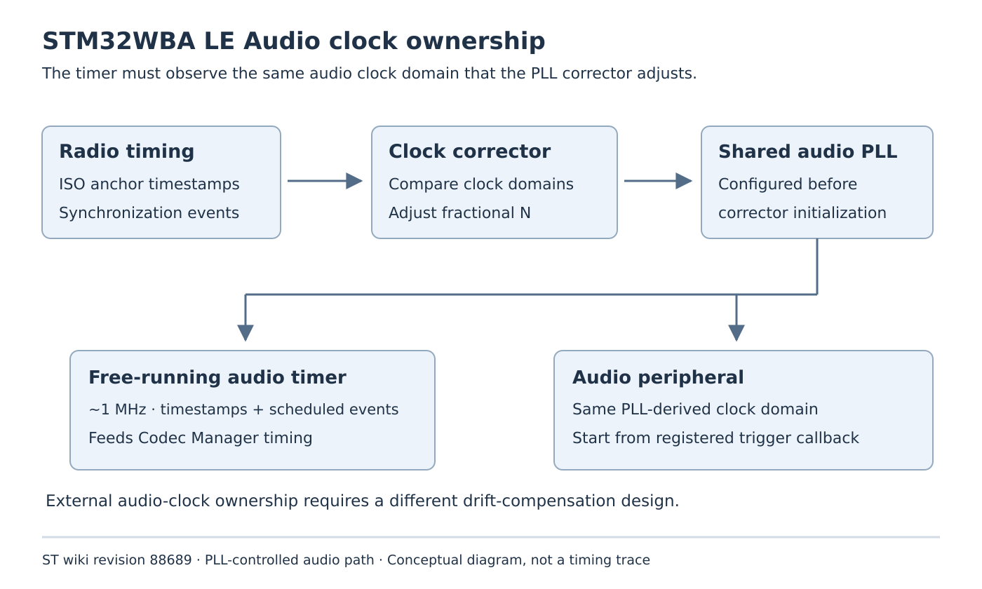
Section 2.2.2 describes ISO anchor timestamps from the link layer and a local timer that measures the relationship between radio timing and the host audio domain. The approximately 1 MHz timer must come from the same PLL output clock as the audio peripheral. The corrector adjusts the PLL’s fractional N value during streaming.
Trace the actual RCC sources and dividers to both consumers. A timer configured to one microsecond per tick from an independent clock is not equivalent merely because its nominal frequency looks convenient. When the corrector changes the audio PLL, the timestamp clock must track the same domain that is being corrected.
Also determine who drives the physical audio clock. The guide explicitly distinguishes an audio interface operating as a target under an external clock; that case requires application-level drift compensation. Moving only the internal timer to the PLL cannot make an externally clocked converter follow the PLL.
Establish the timer and correction hooks before streaming
Section 2.4.5.2 requires CODEC_CLK_Init() before establishing the ISO stream. The timer must be free-running, supply CODEC_CLK_GetHostTimestamp() and support an event requested through CODEC_CLK_RequestTimerEvent(), followed by notification through CODEC_CLK_trigger_event_notify().
Review these as one timing interface. Correct timestamps do not help if a requested event is delivered late or never forwarded. An RTOS scheduling tick is not a drop-in replacement for the specified timer and event mechanism. Preserve the package’s timestamp representation and rollover handling when implementing the callbacks.
The PLL adapter also needs CODEC_CLK_GetPLLNfrac() and CODEC_CLK_SetPLLNfrac(). Initialize the clock corrector with AUDIO_InitializeClockCorrector() after configuring the PLL, supplying the real clock-tree details. Check that no other clock-management path silently overwrites that setup while streaming.
Start the audio transfer at the synchronized boundary
The guide provides CODEC_RegisterTriggerClbk() to register the callback that starts the audio peripheral or DMA in alignment with radio timing. Starting DMA at an arbitrary application-task wakeup and subsequently receiving correct packets does not prove that the intended presentation phase was established.
CODEC_MODE_WAIT_SYNC allows the manager to wait for an initial correction before generating the trigger callbacks. Its use belongs in the selected startup policy; a callback that has not fired yet must not automatically be interpreted as a dead peripheral while synchronization is still pending.
Once running, CODEC_SendData() and CODEC_ReceiveData() are called each frame from the DMA ISR context in this integration. They signal that capture data is ready or that a playback buffer can be refilled. Heavy codec work is requested separately and performed through CODEC_ManagerProcess(). Do not turn the notification callback into an unbounded processing path merely because it runs once per frame.
Separate clock drift from deadline pressure
A proposed diagnostic records radio synchronization events, timer timestamps, trigger callbacks, DMA buffer boundaries, correction changes and codec-processing completion. Use the available low-overhead hooks and retain their clock-domain meaning.
A gradually moving phase or buffer level can motivate examination of the clock relationship. A missed processing deadline under competing CPU load motivates examination of scheduling and controller-delay margins. These are diagnostic hypotheses, not a claim that either trace uniquely identifies a fault.
Section 2.4.4 distinguishes rf_max_setup_time_us, the source radio-preparation allowance, from margin_processing_us, the interruption time budget within a frame. The guide also warns that packets delivered inside the link layer’s preparation window can slip by an ISO event. Finishing LC3 eventually is therefore weaker than finishing before the relevant boundary.
Preserve the application-owned part of latency
The guide separates buffering, algorithmic, transport and presentation contributions. Locally, presentation timing is split between controller and application delay; any nonzero application delay remains the application’s responsibility. The codec trigger does not automatically account for an extra downstream audio stage added by a product.
Document that delay chain without copying a typical total from another use case. Revisit it when changing the converter, buffering, frame settings or processing schedule. A larger buffer may change the available delay range, but it does not correct a mismatched clock source.
Sleep is permitted between processing work only while the relevant audio peripheral and timer continue from the PLL without discontinuities. Qualify any power-management change against that continuity requirement instead of importing a generic low-power sequence.
No audio stream, PLL adjustment or latency measurement was performed here. The acceptance target is a verified clock-and-callback contract: the measured domain matches the corrected audio domain, startup is synchronized, and the application preserves the remaining delay and processing obligations.