Gateway Load Switches: Size Output Discharge for the Next Restart
Turning a peripheral’s supply switch off does not establish that the peripheral has reset. Its local capacitors may retain enough voltage to preserve an undefined internal state, especially when firmware requests another start after a short delay. For a gateway that power-cycles a modem or sensor module, output discharge should be specified against a voltage threshold and dwell time, not against the visual appearance of a falling waveform.
The component example is Texas Instruments’ TPS22918, SLVSD76C, revised July 2017, particularly pages 5 and 13–14. The numerical timing budget below is hypothetical. It does not represent a measured module, a guaranteed reset threshold, or a completed TPS22918 design.
Define what the downstream device requires
Obtain the peripheral’s power-cycle requirements before choosing a resistor. Identify the voltage below which its supply must fall, how long it must remain there, and whether other pins or rails must also be inactive. A GPIO reset command and a full power removal may have different effects.
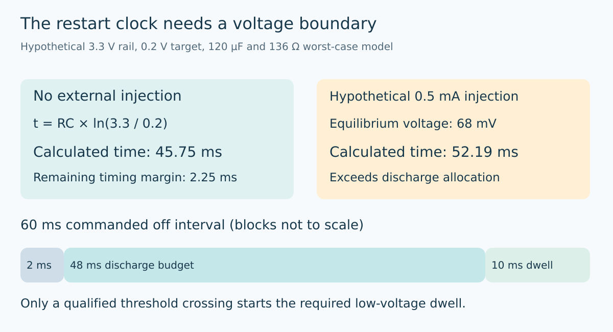
For this example, assume the system specification requires a 3.3 V rail to reach 0.2 V and remain below that level for 10 ms. Assume a 60 ms commanded off interval and allocate 2 ms to control and switch delays. That leaves 48 ms for discharge. These assumed limits must be replaced by the actual peripheral contract.
Measure off time between the relevant electrical events. Software sleep duration can omit command latency, enable propagation, and scheduling variation. A clean restart policy needs an observable boundary, such as enable becoming inactive followed by the rail crossing its required threshold.
Calculate the decay to the required threshold
For a capacitor C discharging through constant resistance R with no other source, voltage follows V(t) = V₀ × exp[−t/(RC)]. Rearranging gives t = RC × ln(V₀/Vtarget). This is a threshold calculation, not the same as a datasheet’s 90–10% fall-time definition.
Suppose the output has 100 µF nominal capacitance and an external discharge resistor of 100 Ω. At 3.3 V input, the TPS22918 table gives a typical internal pull-down resistance of 25 Ω and a maximum of 35 Ω over its stated temperature range. Using the typical total of 125 Ω produces approximately 35.04 ms to reach 0.2 V.
Now use an assumed 120 µF maximum capacitance and a 101 Ω maximum external resistor. With input maintained at 3.3 V, adding the documented 35 Ω maximum internal value gives 136 Ω. The corresponding calculated time is 45.75 ms. Only about 2.25 ms remains against the assumed 48 ms discharge allocation. A nominal waveform would have hidden that narrow margin.
Check the energy and peak-current side
Reducing resistance improves timing but increases the initial discharge current. With a 100 Ω, 1% external resistor, its minimum resistance is 99 Ω. Ignoring the nonnegative internal resistance gives a conservative initial-current upper bound of 3.3 V / 99 Ω, or 33.3 mA, for this isolated-capacitor model.
At 120 µF and 3.3 V, stored energy is approximately 0.653 mJ. That energy must go somewhere during each shutdown. Check the external resistor’s pulse-energy capability, repetition rate, and temperature, plus the switch’s discharge-path limits. A continuous-wattage label is not a complete short-pulse specification.
The TPS22918 also places a 200 µF limit on the capacitive load when only its internal pull-down is used; larger loads require an appropriate external resistor. That device-specific condition is not a universal load-switch rule. Verify the selected part’s actual restrictions rather than importing another part’s resistance or thermal assumptions.
Account for a second source on the supposedly off rail
The exponential model assumes no ongoing injection. A powered interface, another supply, or a module signal can invalidate that assumption. Identify possible back-power paths before treating a long discharge as simply “too much capacitance.”
For a constant hypothetical injected current Iback, the resistance produces an equilibrium voltage Veq = Iback × R. The decay becomes Veq + (V₀ − Veq) × exp[−t/(RC)]. At 0.5 mA and 136 Ω, Veq is 68 mV. With the same 120 µF, the calculated time to 0.2 V grows to about 52.19 ms, exceeding the 48 ms allocation.
At 0.2 V / 136 Ω, approximately 1.47 mA, the equilibrium reaches the target itself. Above that injection, this model never crosses below the target. Merely waiting longer cannot solve that condition. Real injection is often voltage-dependent, so this constant-current example is a diagnostic model, not permission to drive the discharge path continuously.
Separate controlled shutdown from total power loss
A stable input supply with the switch disabled is one case. Removing the input supply at the same time is another. TPS22918 documentation warns that its internal discharge strength decreases as input voltage falls. A fixed-resistance estimate therefore cannot be assumed valid throughout an uncontrolled input collapse.
Test both cases if the product must support both. Capture input voltage, output voltage, enable, and any still-powered interfaces. Use the intended connector sequence and documented current-limited fixtures. Do not short a capacitor to force a faster reset or defeat a protection feature during testing.
If a second source is present, address that source or choose an architecture intended for the required power sequencing. Do not ask the quick-discharge FET to act as an unrestricted load for another supply.
Make restart eligibility explicit
A robust controller distinguishes “off requested,” “rail below threshold,” “minimum dwell complete,” and “restart permitted.” Where direct sensing is unavailable, its delay must cover the worst supported component and operating conditions with justified margin.
Retain the capacitance estimate, resistor tolerances, input-voltage cases, back-power checks, and threshold evidence. Successful communication after one restart is useful but does not prove that every supported off interval resets the module. The engineering result is a bounded restart contract: the rail actually becomes low enough, stays low long enough, and does so without overstressing the discharge path.
Topic provenance
The preserved Google Trends RISING row “industrial iot solutions,+110%,” worldwide, all categories, web search, July 19–October 19, 2026 supports the parent integration topic only. It does not establish search growth for this electrical mechanism or article title.