SDI-12 Gateway Hardware: Validate the Shared Data Line Before Debugging Sensor Commands
A water-monitoring gateway that receives nothing from a sensor does not necessarily have a command-parser problem. SDI-12 combines a particular electrical interface with serial framing and command timing. Reusing an ordinary MCU UART header without reviewing the bus can produce a design that looks correct in source code but cannot communicate reliably through the intended harness.
For an embedded product team, the useful starting point is a recorder-side electrical acceptance plan. This article uses the SDI-12 Version 1.4 specification dated January 30, 2021. It focuses on the shared data connection and installation boundary, not on building a complete protocol stack or claiming conformity from a few measurements.
Three conductors do not mean a generic serial port
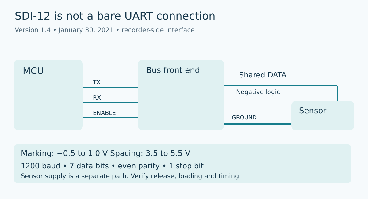
The specification defines a shared data line, ground, and nominal 12 V supply connection. The data line is bidirectional and uses negative logic. Its specified marking range is −0.5 to 1.0 V; spacing is 3.5 to 5.5 V. The supply connection has its own requirements and must not be confused with the data voltage.
Those facts immediately change the schematic review. Ask which circuit translates between the MCU and bus polarity, which circuit receives the bus levels, and which control releases the transmitter. Do not infer compatibility from a microcontroller pin’s label or from the sensor supply voltage. Any direct connection must be justified against the selected device’s documented input and output limits.
A useful drawing shows three separate paths: MCU transmit to bus driver, bus to MCU receive, and driver-enable control. Add the sensor supply path separately. This makes it harder for a review to approve only the UART peripheral configuration while overlooking the electrical interface that actually touches the cable.
Release behavior is an analog requirement
The standard specifies transmitter source resistance above 1 kΩ and below 2 kΩ while transmitting. With the transmitter off, resistance to ground is specified between 160 kΩ and 360 kΩ. It also limits normal-operation voltage slew rate to 1.5 V per microsecond. These are not captured by choosing the UART’s baud rate.
Turn those requirements into explicit design checks for the selected circuit. Review the enabled driver path, the disabled path, and the effect of protection components. A high-impedance MCU configuration alone is not a complete explanation of the bus’s off-state resistance. Conversely, a resistor that provides a plausible idle voltage may still create an unintended load when several devices share the bus.
Measure both command transmission and sensor response with the production front end installed. The acceptance evidence should show that the recorder stops driving in time for the sensor, not merely that its firmware writes a disable bit. Include a scope capture at the bus connector and, where useful, a separate capture at the MCU receive pin. Comparing the two can localize a polarity or translation problem without changing the command sequence.
Test the installed cable, not only the board connector
Cable loading belongs in the product requirement. The standard relates maximum cable length to total connected cable capacitance. A short laboratory jumper is therefore a weak substitute for the intended branched installation. Specify the sensor count, cable arrangement, and relevant cable characteristics that the product will support.
Build a representative harness and record where measurements are taken. Compare the recorder connector with the far sensor connection. If a transition becomes marginal only at the far end, changing a parser timeout may hide the symptom without addressing the electrical cause. Use measured waveforms and the chosen circuit’s limits to guide changes rather than increasing retries until a demonstration appears stable.
The shared ground also deserves a measurement point. For the intended maximum sensor load, measure the difference between recorder ground and sensor ground. Keep power-conductor sizing, connection resistance, and supply behavior in the installation review. A good waveform measured only relative to local recorder ground does not describe every sensor’s view of the bus.
Verify framing after the physical path is credible
The specified serial format is 1200 baud with seven data bits, even parity, and one stop bit. A break is at least 12 ms of continuous spacing. These are compact requirements, but they are easy to lose when a driver abstraction assumes a conventional eight-bit, no-parity serial stream.
A proposed bring-up sequence first captures a known transmitted frame and checks polarity, bit period, parity, and stop behavior at the connector. Then verify the break and the subsequent command timing against section 7 of the specification. This article does not replace that timing section with an abbreviated universal delay recipe.
Only after that should the team interpret the sensor’s response at the command layer. Log the addressed command, observed bytes, and framing errors separately. A missing response, a parity error, and a syntactically invalid payload are different observations. Keeping them separate prevents firmware from turning every physical-interface defect into the same unhelpful “sensor unavailable” message.
Define what happens during product transitions
The schematic and test plan should identify the bus state during MCU reset, startup, and firmware reconfiguration. These are engineering acceptance questions, not additional timing rules claimed from the specification. Determine whether driver-enable has a defined hardware default and whether initialization can briefly drive an unintended level.
Also check the product’s intended power arrangement. If sensors can remain powered while the recorder is off, characterize the resulting interface state with the actual front end. Review component absolute limits and possible back-power paths before running that condition. Do not assume that behavior demonstrated with all devices powered applies when only one side is alive.
For outdoor water or process instrumentation, protection and grounding decisions require their own system review. The protocol document’s suggested circuits are not proof that a particular board has passed surge, environmental, or safety qualification. State what was tested and leave certification claims to the applicable assessment process.
Release a bounded interface contract
An Obeita gateway handoff should include the electrical schematic, supported harness envelope, power arrangement, framing configuration, and annotated connector-level captures. Keep a known-good sensor and harness configuration with the acceptance procedure. That gives manufacturing and integration teams a reproducible starting point rather than a collection of unexplained retry settings.
The central distinction is simple: a valid command can travel through an invalid interface. Establish the electrical path first, then verify protocol timing and measurement behavior. The proposed tests here are not reported experiments, and passing them alone does not establish full SDI-12 compliance.
Source and topic provenance
Primary source: SDI-12 Support Group, SDI-12 Version 1.4, January 30, 2021, sections 3, 4.1, and 7: SDI-12 Version 1.4, January 30, 2021, sections 3, 4.1 and 7
Topic selection uses the preserved Google Trends RISING row “industrial iot solutions,+110%,” Worldwide, all categories, web search, July 19–October 19, 2026. This is parent-topic evidence only, not a measured rise in SDI-12 searches or demand for this article.