Modbus Coil Bit Packing: Test Boundary Addresses and Unused Response Bits
For Modbus Read Coils and Read Discrete Inputs, the first requested item occupies bit zero of the first response data byte. Subsequent items advance toward bit seven, then continue at bit zero of the next byte. The mapping is relative to the request’s starting address; it is not aligned to an absolute eight-address boundary.
This guide pins Modbus Application Protocol V1.1b3, 26 April 2012, sections 6.1 and 6.2. It covers functions 01 and 02 and their normal response PDUs. An original Python encoder/validator was executed offline. No serial capture, device map or production parser was tested.
Keep three ordering questions separate
The two-byte starting address and quantity fields use the protocol’s most-significant-byte-first representation. The coil data itself packs individual boolean items from the least significant bit upward. Neither rule describes a vendor’s multi-register floating-point arrangement.
Do not swap response bytes as though they were a 16-bit register. Do not apply an absolute-address modulo-eight shift either. Even if the starting PDU address is five, the requested item at address five is returned in bit zero of the first data byte, not bit five.
Functions 01 and 02 use separate logical tables: coils and discrete inputs. The same address and bit-packing formula do not establish that those tables represent the same physical signal. Confirm the function and zero-based PDU address against the device’s documented map.
Derive the mapping from the outstanding request
Let the requested start address be A and quantity be Q. For an item offset i, with zero less than or equal to i and i less than Q, its PDU address is A+i, its response data-byte index is floor(i/8), and its bit position is i modulo eight.
item[i] = (data[i / 8] >> (i % 8)) & 1
expected_data_bytes = (Q + 7) / 8
These expressions use integer division and were exercised by the offline model. In a C implementation, validate Q before arithmetic and use suitable unsigned types. The normal response does not repeat A or Q, so retain the admitted request context instead of guessing the quantity from the final byte.
The specification permits one through 2,000 requested items, producing at most 250 data bytes. Also ensure the requested address span does not run beyond the 16-bit address space or the device’s implemented region. A protocol-valid span is not proof that a particular controller implements it.
An original cross-byte example
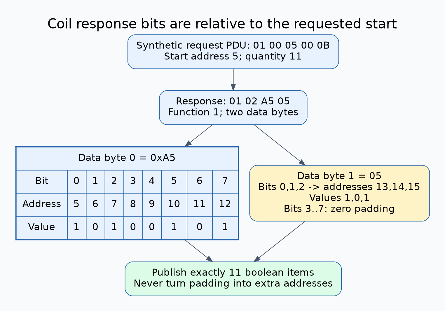
Consider a hypothetical request for eleven coils starting at PDU address five. Its request PDU is 01 00 05 00 0B. Suppose the synthetic normal response PDU is 01 02 A5 05: function one, byte count two, then two packed data bytes.
| Data byte | Bit positions used | PDU addresses | Items set in this example |
|---|---|---|---|
| 0xA5 | 0 through 7 | 5 through 12 | 5, 7, 10, 12 |
| 0x05 | 0 through 2 | 13 through 15 | 13, 15 |
The remaining five high bits of the final byte are padding, not additional coils. A decoder that emits sixteen results invents five observations the request never asked for. A decoder that reverses the bit order changes the signal identities even though the byte count and transport checksum can remain valid.
Validate the shape before publishing any booleans
- Confirm the response belongs to the outstanding device/transaction through the selected transport’s association checks.
- Separate exception responses from normal function 01 or 02 responses.
- Derive the required byte count from the validated requested quantity.
- Require the normal response’s byte-count field and actual PDU length to match that requirement exactly.
- When Q is not a multiple of eight, check the unused upper bits of the last byte against the specification’s zero-padding requirement.
- Decode exactly Q items, then attach their addresses and function-table identity before application dispatch.
For a complete normal PDU, the expected size is two plus the packed-data byte count. Extra bytes are not permission to extend the result. On TCP, an accumulator must first establish the complete PDU using the enclosing message framing; on RTU, framing and CRC remain separate validation layers.
Make padding failures visible
The standard requires zero padding toward the high end of the last byte. The supplied validator rejects nonzero unused bits before producing a result. If an integration deliberately tolerates a known nonconforming device, document that compatibility policy and still prevent unused bits from becoming application data.
Do not silently reinterpret dirty padding as a larger quantity. Preserve the requested Q, actual count and offending last byte for diagnosis. Distinguish a padding violation from an incomplete response or a response to a different request; each needs different evidence.
Executed regression and target acceptance
The offline fixture generated and decoded both function codes for every quantity from one through 2,000, totaling 4,000 round trips. A repeating boolean pattern exercised positions within and across bytes. The eleven-item example produced the six set addresses listed above.
Additional cases accepted address 65,535 with quantity one and rejected a span that crossed the address-space end. Eight invalid cases covered request bounds, dirty padding, mismatched count, truncation, trailing data and the wrong normal function. These tests establish the original validator’s decisions, not exhaustive Modbus conformance.
On the actual target, choose documented read-only observation points or a simulator. Exercise quantities one, seven, eight, nine and a supported larger boundary, including a non-byte-aligned start. Compare known signal changes with the exact PDU-address list rather than a packed integer display.
Archive the device map revision, transport, request bytes, response bytes and decoded address/value pairs. The acceptance result should explain every returned bit and every unused bit. That is the evidence needed to separate a coil-indexing defect from register endianness, a wrong map or a physical input that never changed.