Linux RS-485 Direction Control: Verify RTS Polarity and Turnaround on the Wire
A successful RS-485 configuration ioctl does not prove that the transceiver drives and releases the bus at the correct times. Qualify direction control with two records: the settings actually accepted by the driver and a capture that relates those settings to UART data, driver enable and the differential bus. Treat unsupported controls as a capability limitation, not a reason to keep increasing delays.
This guide is scoped to Linux 6.6 serial_rs485 interfaces and a two-wire half-duplex product whose UART driver exposes those controls. It does not assume that every USB adapter, UART or vendor kernel implements them. The board schematic and the selected transceiver’s datasheet determine the electrical meaning of the control signal.
Trace the direction path before setting polarity
Identify the physical route from the UART or GPIO to the transceiver’s driver-enable input. Include any inverter, isolator, buffer and programmable pin multiplexing. Determine whether receive enable is separately controlled, tied to direction control or permanently asserted. A software signal named RTS is not enough to establish the polarity at the transceiver.
For half-duplex operation, the bus needs controlled driver ownership. Texas Instruments’ RS-485 Design Guide, SLLA272D, revised May 2021 explains the role of direction-control signals in avoiding simultaneous drivers. This guide focuses on that ownership interval; termination and bias-network design are separate investigations.
Write a short truth table from the actual board: requested logical send level, measured control-pin level, and expected driver state. If those relationships are unknown, stop before sending into a live multidrop network. Resolve the schematic and component documentation first.
Read the accepted configuration, not only the request
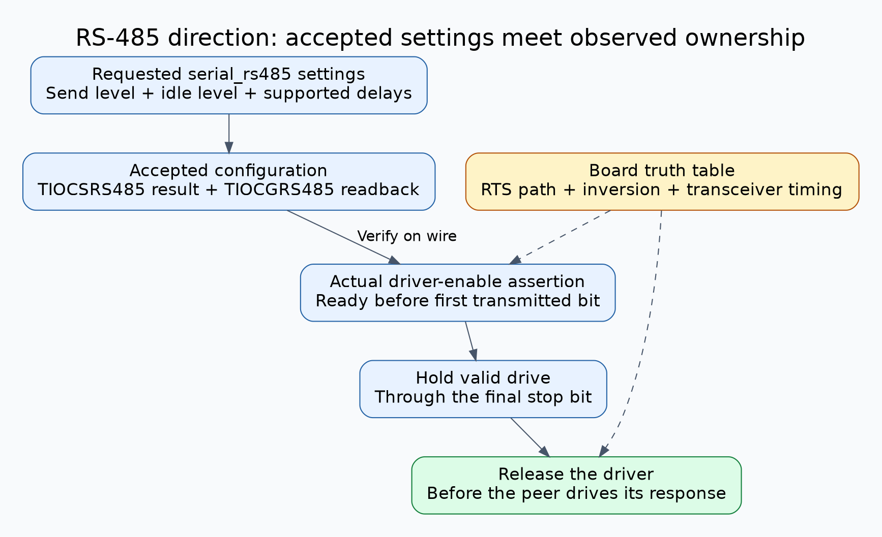
Linux 6.6 uses TIOCSRS485 to configure serial_rs485 and TIOCGRS485 to read its current state. The serial core sanitizes requested settings against driver-supported features before invoking the driver configuration callback. The set operation returns the resulting state with unsupported bits adjusted. These behaviors are documented in Linux 6.6 RS-485 serial communications.
Build a diagnostic record with the device node, kernel build, driver identity, initial configuration, requested configuration, return value, error code where applicable, and readback. Preserve the request separately so that an in-place returned structure does not overwrite the evidence of what was attempted.
The same interface defines RTS_ON_SEND and RTS_AFTER_SEND as logical RTS levels, and both delay fields are expressed in milliseconds. They are not universally available microsecond controls. Zero-initialize any request structure and its reserved fields, and change only the controls needed for the experiment. Check the driver-specific meaning and supported resolution rather than assuming every integer delay is implemented exactly.
If a required flag is absent after readback, or the ioctl is unsupported, classify the requirement as unmet for that driver path. Do not substitute ad hoc user-space RTS toggling and label it equivalent without its own timing design and qualification.
Capture the minimum electrical evidence
Use an isolated bench segment and suitable measurement equipment. Choose probes and grounding appropriate to the board’s voltage, isolation and common-mode conditions; do not connect an earth-referenced probe in a way that defeats an isolation barrier. A differential bus capture plus local logic observations is preferable to inferring bus behavior from application timestamps.
Capture the UART transmit signal, the actual driver-enable control at the relevant side of any isolation, and the bus waveform. If practical, capture the peer’s transmit-enable signal and the local receive data as well. Trigger on a recognizable request that exercises both the first and final byte boundaries.
Mark four events: driver assertion, first transmitted start bit, completion of the final stop bit, and actual release of bus drive. Then locate the peer response. Use the transceiver’s specified enable/disable behavior to interpret the control edge; a logic transition at an upstream GPIO is not automatically the instant the bus reaches high impedance.
Run a one-variable turnaround experiment
- Record the baseline driver configuration and confirm the bench peer is the only intended responder.
- Apply the intended send and idle levels, then read them back. If readback differs, resolve support before timing analysis.
- Send a short, known request and confirm that the first byte appears intact on the bus.
- Check that drive remains valid through the final stop bit, including the longest relevant request and transmit path.
- Check release against the peer’s earliest supported response. Look for overlapping drive or a response that begins while the local driver remains active.
- Change one supported delay or polarity control only when the capture predicts how that change should help.
- Repeat with different request lengths, relevant baud settings, application write chunking and representative host load.
The procedure is proposed and has not been executed on a target here. Write completion, buffer emptying and electrical transmission completion are distinct observation points. Keep host timestamps as useful context, but let the wire capture establish whether the final bit was driven correctly.
Interpret common mismatches without hiding them
- Enable arrives after the first start bit: investigate the direction-control path and supported pre-send timing.
- Enable drops before the final stop bit finishes: inspect the driver’s transmit-completion condition and post-send behavior.
- Local drive persists into the peer response: examine the accepted post-send delay and electrical disable path; more delay would worsen this case.
- Readback is correct but polarity at the transceiver is wrong: reconcile inversion, pin multiplexing and schematic assumptions.
- Received data resembles the transmitted request: distinguish local echo from a peer reply using the direction and bus trace.
A bus returning to an idle voltage does not, on its own, prove that a particular transceiver has released it. Other drivers or bias circuitry can produce an idle-looking level. Correlate control behavior, device timing specifications and a carefully designed peer-response test before claiming electrical ownership is correct.
Hypothetical example: a post-send delay masks the first fault
Consider a hypothetical gateway whose last transmitted byte is occasionally clipped. A developer adds a large post-send delay. The request then looks intact, but the fastest peer begins replying while the gateway is still driving. The application reports intermittent response corruption.
The useful investigation preserves both captures: the original early-release failure and the new late-release failure. Readback shows whether the requested delay was accepted; the wire evidence identifies the window that the implementation must satisfy. The eventual correction might involve the driver’s completion logic or a supported hardware direction mode rather than a larger constant.
Accept the product only when the supported configuration, polarity truth table and observed ownership interval agree across the required operating cases. Retain those records with the kernel and board revisions so a later driver or hardware change can be qualified against the same contract.