STM32G431 and G474 FDCAN: Budget the Fixed Message RAM Before Bus Load
The STM32G431 and STM32G474 use an FDCAN integration with a small, specified message-RAM layout. A generic M_CAN example that allocates a large receive FIFO is not automatically a valid configuration for these devices, and spare application SRAM does not establish additional controller capacity.
The relevant hardware layout is RM0440 Rev 9, section 44.3.6 and Figure 670. The G431 datasheet identifies one FDCAN instance; the G474 datasheet identifies three. Controller count and buffering depth are separate design constraints.
Read the fixed layout before copying initialization code
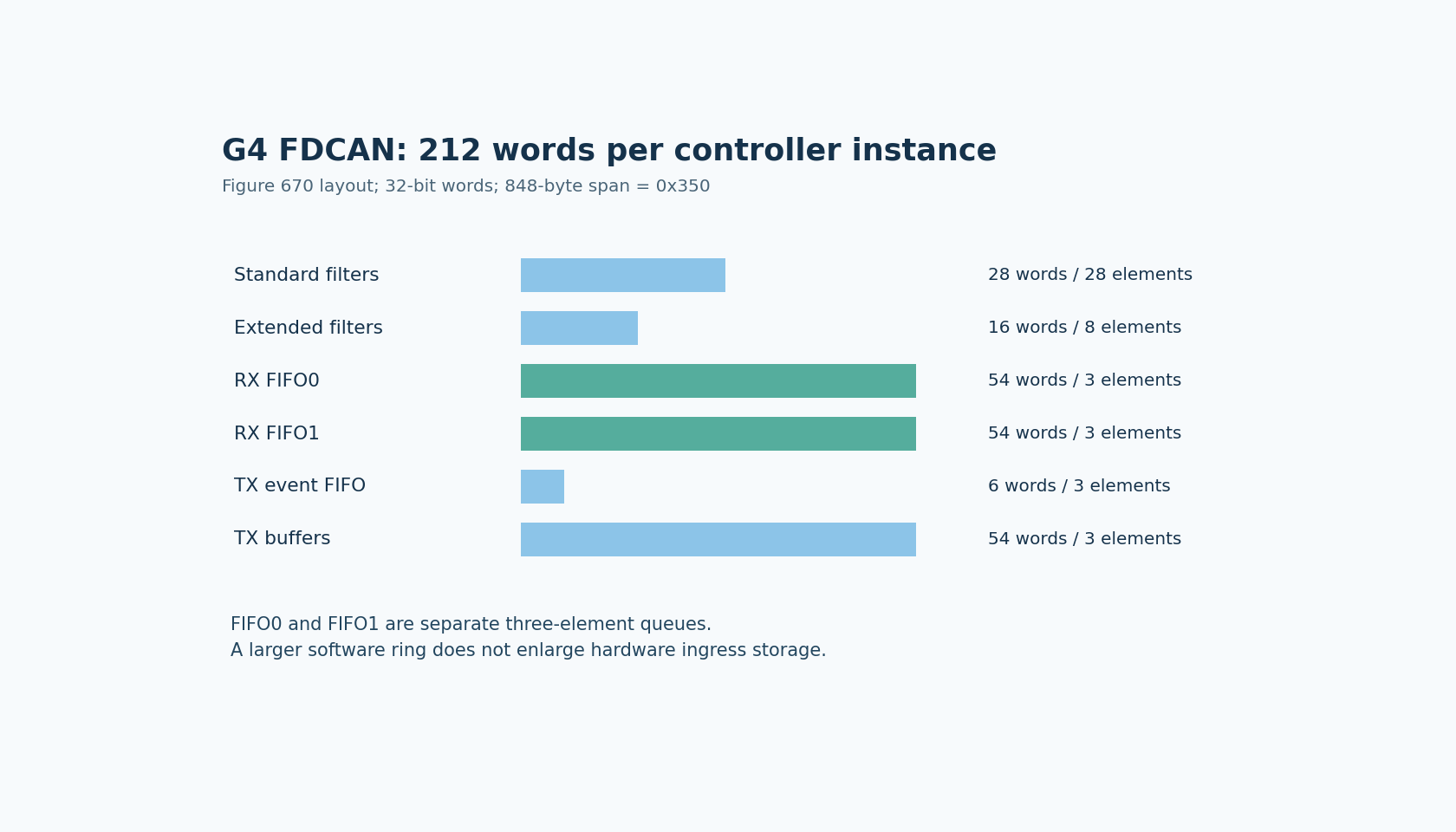
Figure 670 assigns 212 32-bit words to an instance. It shows 28 standard-filter elements using 28 words, eight extended-filter elements using 16 words, and three elements in each of the two receive FIFOs, each FIFO using 54 words. The transmit-event FIFO has three elements using six words, and the transmit-buffer area has three elements using 54 words.
Adding those areas gives 212 words, or 848 bytes. That arithmetic is a restatement of the documented layout, not a measured memory allocation or an invitation to rearrange the sections.
For multiple instances, the next start address follows the previous end address by four bytes. The per-instance span is 0x350 bytes. Consequently, the presence of three controllers on G474 should not be interpreted as a documented mechanism for donating two unused controllers' storage to the first controller.
Separate hardware ingress from the software queue
A software ring buffer becomes useful after firmware has removed a frame from the peripheral's receive storage. Increasing that ring can absorb a downstream processing delay. It does not, by itself, absorb a period during which nothing drains the hardware FIFO.
Consider a deliberately simplified workload: four accepted frames arrive for FIFO0 while it starts empty and no frame is removed. A three-element FIFO cannot simultaneously retain all four. The resulting loss or overwrite behavior depends on the configured mode and must be handled according to the manual and driver; this capacity argument does not identify which frame the application eventually receives.
The important quantity is accepted arrival backlog minus completed removals. Average bus utilization is insufficient if the worst permitted burst can exceed the available queue depth during a service gap. Interrupt masking, other high-priority work and the receive handler's execution time therefore belong in the buffering budget.
No bus-load experiment was run here. This is a proposed admission calculation that can reject an impossible buffering assumption before hardware testing.
Filters allocate traffic as well as identifiers
The manual describes two acceptance-filter lists and states that evaluation stops at the first matching element. Filters can direct accepted frames to FIFO0 or FIFO1. Their order and destination therefore affect which queue receives a burst.
A design may separate classes of traffic across the two FIFOs, but six total receive slots do not behave like one automatically shared six-slot queue. Four frames routed to FIFO0 can exhaust that FIFO while FIFO1 remains empty.
Review overlapping filters in order. A broad earlier match can send traffic somewhere different from a narrower rule later in the list. Evaluate the complete acceptance configuration, including what happens to nonmatching traffic, rather than counting only the filter entries an application deliberately added.
The number of filter elements also differs from the number of admitted identifiers: range and mask rules can cover more than one identifier. The useful budget is the traffic admitted by the complete rules, not a one-filter-equals-one-frame assumption.
Make the driver prove it targets this integration
Inspect the selected driver's device-specific configuration and constants. Confirm that its register setup and message-RAM assumptions match RM0440 for G431 or G474. A portable API may expose options that require different hardware support on another MCU family.
Do not bypass a driver restriction merely because another M_CAN implementation permits a larger FIFO. Establish the target hardware contract first. Conversely, an application-side queue limit should not be mistaken for a hardware limit; identify which layer owns each capacity field.
Keep transmit buffering and transmit-event tracking in their own rows. Their three-element areas serve different purposes from receive FIFOs, so summing every message-RAM element into one apparent queue length is misleading.
Validate the service budget on an isolated fixture
A later qualification should record the accepted traffic pattern, destination FIFO, longest drain gap and observed loss/status indications. Use a controlled, inert CAN setup rather than stressing an operating machine. Include bursts that target one FIFO and overlapping-filter cases, not only a uniform stream.
If the requirement does not fit, the available decisions include reducing admitted traffic, reducing service latency, changing workload scheduling or selecting hardware with a suitable buffering architecture. A larger software ring is justified only when the bottleneck is actually downstream.
The deliverable is a queue-capacity and service-latency argument tied to this exact controller integration. It prevents a familiar mistake: treating application RAM capacity or a generic controller example as evidence that the peripheral can retain a burst while firmware is absent.