ifm VSE152 Variable-Speed Monitoring: Connect EtherCAT Speed Data to the Measurement Context
A PLC can receive a plausible vibration value while the diagnostic
object is outside its intended operating conditions. For an ifm VSE152
monitoring a variable-speed machine, integration includes the speed sent
to the diagnostic unit, the trigger that uses it, and the status
returned with the result. Transferring the vibration number alone leaves
that context unresolved.
This discussion uses VSE152 operating instructions 11441755/02,
October 2026, and the VES004 2.38 software manual. It addresses
frequency-selective monitoring configured to use an external speed
input; it does not claim that every vibration object needs the same
trigger or working range.
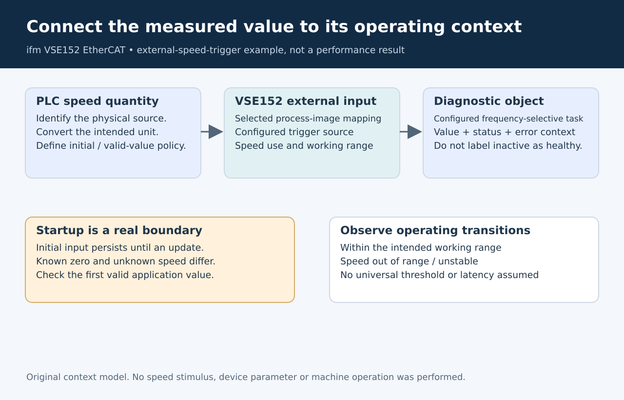
Original measurement-context model. No machine speed, vibration
response or diagnostic performance was measured.
Start with the
two directions of the interface
The VSE152 EtherCAT data model includes external-input values in the
PLC’s output direction. Its PLC inputs can include the external value,
an object’s value, its status and error information, and the rotational
speed used by the trigger. Select the required items in the actual
VES004 process image. VSE152
manual, section 13.1.7
That creates a useful evidence loop: what the PLC intended to send,
what value the device exposes, and which context qualifies the returned
diagnostic result. It does not establish simultaneous sampling across
the machine or a common timestamp. Those stronger requirements need
additional, implementation-specific evidence.
Name the physical speed source as part of the interface. A
motor-speed command, measured motor speed and a downstream shaft’s
actual speed can represent different quantities. The configuration must
identify which quantity the selected diagnostic calculation expects; a
tag containing the word “speed” is insufficient.
Define units and
the startup value together
VES004’s external-input configuration gives the signal a unit and an
initial value. The manual says that the unit must correspond to the
transmitted variable and that the initial value remains in use after
initialization until an interface update replaces it. VES004
manual, section 9.3.2.4
For a hypothetical interface, 30 revolutions per second equals 1,800
revolutions per minute. Sending the number 30 where the configuration
expects rpm creates a different operating condition. Resolve the
conversion in the interface contract and verify the selected
representation. A human-readable unit label is not sufficient evidence
that the producer’s number was converted correctly.
Also define when the PLC begins supplying a valid value after
startup. Do not let the diagnostic unit’s initialized value silently
stand in for established machine-speed information. The application must
distinguish “speed is known to be zero” from “the current speed has not
been supplied.”
Bind the
trigger to the intended operating range
The software manual allows an external input to supply a trigger for
variable-speed, frequency-selective monitoring. Its configuration
distinguishes use as a rotational-speed signal from use as a
reference-value trigger. For external or analogue sources, the working
range determines when the trigger condition is met. VES004
manual, sections 9.3.3.2–9.3.3.4
Review that selection with the intended object, rather than assuming
that creating an external input automatically connects it to every
diagnostic calculation. A correct number in the process image can
coexist with an object using a different trigger source or operating
range.
Choose the range from the monitoring task and machine behavior. This
article supplies no universal speed band, settling time or
bearing-detection threshold. Qualification should include the intended
steady operating condition and relevant transitions into and out of
it.
Return a qualified
result to the application
The VSE152 model distinguishes an object’s inactive and error states
from its normal and alarm states. Its error information includes speed
outside the range and unstable speed. Preserve that distinction in the
PLC and operator display; an unavailable calculation should not be
silently rendered as a healthy measurement.
For an approved fixture, compare startup before the first valid speed
update, operation inside the configured range, and a transition outside
it. Observe the returned context alongside the value. The resulting
acceptance evidence should show that a diagnostic result belongs to the
intended operating condition, rather than merely proving that EtherCAT
transported a number.