Modbus RTU over TCP Is Not Modbus TCP: Identify the Frame Format Before Integration
A successful TCP connection does not establish that two devices speak the same Modbus framing. One side may expect an MBAP header while the other sends a complete RTU message, including its CRC. Both products can advertise “Modbus over Ethernet,” yet neither understands the bytes it receives. Identify the actual application data unit before changing baud rates, register offsets or retry settings.
This comparison uses Modbus Application Protocol V1.1b3, TCP/IP Implementation Guide V1.0b and Serial Line V1.02. “RTU over TCP” is used here for a documented vendor tunnel carrying RTU-format bytes; the phrase alone is not a complete interoperable transport specification.
Ask for bytes, not a marketing protocol name
Request the client configuration, gateway mode, firmware revision and one documented request/response example. Ask whether the TCP payload begins with MBAP, contains a serial slave address, includes a CRC, or adds any proprietary prefix. Check both directions; a gateway that converts requests may also transform replies.
A TCP port number is useful configuration evidence but cannot prove the payload format. Port 502 is associated with Modbus TCP, while products may provide configurable services. Likewise, a packet analyzer’s selected decoder is an interpretation, not independent evidence that the device is configured correctly. Keep the raw byte sequence beside the decoded view.
Recognize the common PDU and different wrappers
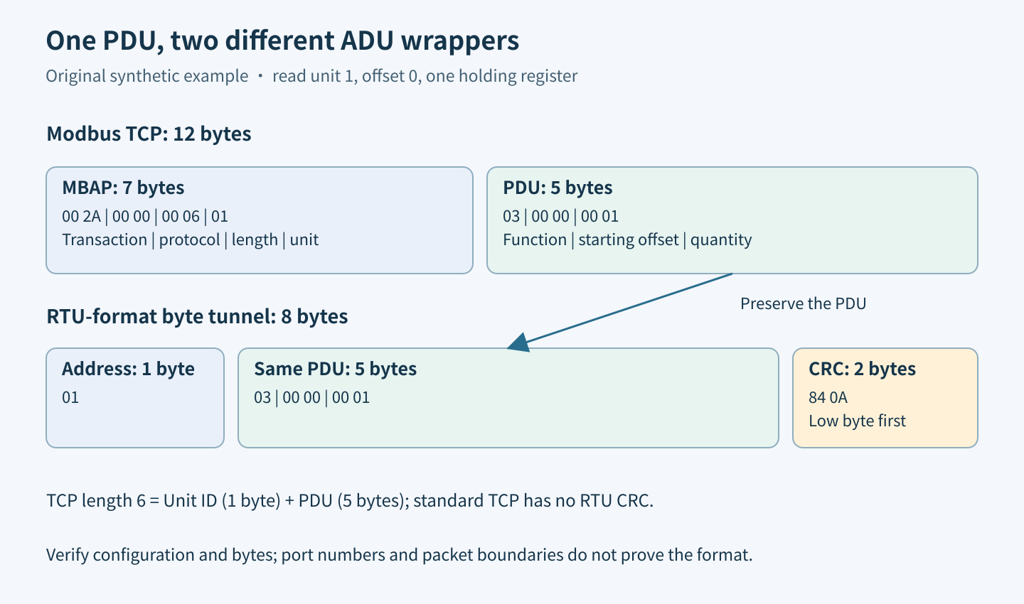
The Modbus PDU consists of function code and function data. An RTU ADU adds a slave address before it and a two-byte CRC after it. A Modbus TCP ADU instead adds the seven-byte MBAP header; it does not append the RTU CRC. These boundaries are defined in the application specification, section 4.1, and the TCP implementation guide, section 3.1.
Use precise names in interfaces. Calling the complete RTU frame a “PDU” can lead a conversion routine to preserve the address and CRC when it should preserve only the function and data. For standard framing, the maximum PDU is 253 bytes, the RTU ADU 256 and the TCP ADU 260. Vendor tunnel headers are additional, separately documented framing.
Walk through one synthetic request
Choose a hypothetical read of one holding register at wire offset zero, addressed to unit one. Its PDU is 03 00 00 00 01. For Modbus TCP, using transaction ID 0x002A, the entire request is 00 2A 00 00 00 06 01 03 00 00 00 01. The length field is six because it counts Unit Identifier plus the five-byte PDU, not the entire twelve-byte ADU.
The equivalent RTU request is 01 03 00 00 00 01 84 0A. Its CRC is transmitted low byte first, as specified in Serial Line V1.02, section 2.5.1 and appendix B. The CRC bytes belong to the RTU wrapper. Do not add them to the TCP example, and do not treat the TCP transaction ID as a serial address.
Capture a safe exchange at the right boundary
Begin with a simulator or an isolated device whose register documentation permits the selected read. Some vendor objects have read side effects, so “read-only function” is not a substitute for checking the device map. Record the configured unit, wire offset, quantity and expected response type before capturing.
Capture the TCP application stream in each direction and, when authorized equipment is available, the gateway’s serial output separately. If the gateway converts protocols, the two byte sequences should intentionally differ. Compare the common PDU and address mapping rather than demanding identical complete frames. Save the gateway configuration with the trace so the conclusion remains reproducible.
Do not mistake TCP delivery chunks for framing
TCP can deliver one application message through several reads or several messages through one read. For Modbus TCP, the MBAP length contributes the application boundary. For a raw RTU-byte tunnel, the integration contract must explain how the receiver recognizes messages and handles partial data; an Ethernet packet boundary is not an RTU delimiter.
Nor does a transparent byte stream preserve the original serial inter-character timing. A pause between host reads may reflect buffering rather than silence on the serial wire. This article’s identification method compares byte layouts, not RTU timing compliance. If timing preservation is a requirement, specify and validate it independently at the serial boundary.
Reject mismatches before trying alternative formats
A receiver expecting MBAP may interpret RTU bytes as an impossible protocol identifier or length. A raw-tunnel peer may forward MBAP bytes toward the serial bus, producing no valid slave response. These are hypotheses to confirm from captured bytes, not reasons to assign every timeout to a framing mismatch.
Prefer explicit protocol mode selection. Automatically switching formats after one malformed message is especially risky for writes: the alternate interpretation may become a different valid command. Keep probes non-mutating, bound any identification buffer, and require a reviewed configuration change before forwarding a newly interpreted format to real equipment.
Deliver an unambiguous integration record
- Name the exact upstream wire format and downstream serial format.
- Include one complete annotated request and response, with PDU boundaries.
- State who adds or removes MBAP, serial address and CRC.
- Define length handling, supported functions, Unit Identifier mapping and malformed-format behavior.
- Verify that the chosen client mode matches the saved gateway firmware configuration.
The acceptance result should say “these bytes match this configured framing,” not merely “the port connects.” A valid example confirms the selected exchange only. It does not establish support for every function, prove device register semantics or make a vendor-specific tunnel equivalent to standard Modbus TCP.