Modbus CRC Byte Order: Separate Wire CRC from Register Endianness
Changing a floating-point word-order setting cannot repair a CRC check performed on the wrong bytes. Modbus RTU has several ordering rules at different layers: individual data fields, vendor-defined multi-register values, the CRC calculation, and the two CRC bytes placed on the wire. A useful investigation gives each rule its own name and test.
The normative boundary in this guide is Modbus Serial Line V1.02 with Application Protocol V1.1b3. The supplied examples are reproducible software calculations, not captures from an instrument. They establish checksum behavior only; they do not validate an electrical link or a register map.
Confirm that the selected framing actually uses this CRC
RTU uses a two-byte CRC at the end of its serial ADU. Modbus ASCII uses LRC, while standard Modbus TCP uses MBAP and does not append the RTU CRC. A vendor tunnel may carry the RTU frame unchanged. Identify the configured format before deciding which trailing bytes are checksum bytes.
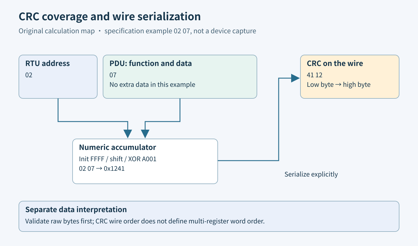
For RTU, cover the address, function and data bytes, excluding the CRC being generated. UART start, parity and stop bits are not input bytes. The serial guide, section 2.5.1 and appendix B, defines this calculation boundary. If a software log adds timestamps, separators or hexadecimal text, decode the original binary values first; the characters “0” and “2” are not the single byte 0x02.
Specify the helper’s numeric return convention
A straightforward reflected bitwise implementation starts at 0xFFFF, processes each byte through eight right shifts and conditionally XORs 0xA001. Document that its return is the numeric accumulator, then serialize explicitly: first accumulator AND 0xFF, then accumulator shifted right eight bits. Avoid copying a native integer directly into a transmit buffer.
Some APIs or legacy table implementations expose a pre-arranged representation instead. Do not add a second swap merely because a function is named CRC16. Compare its documented return value and emitted byte pair separately. CPU endianness, printed hexadecimal order and wire order are three different observations, even when two happen to agree on a development machine.
Use the specification’s short example as an oracle
Appendix B works through input bytes 02 07. With the numeric-accumulator convention above, the result is 0x1241 and the transmitted pair is 41 12, making the complete illustrative frame 02 07 41 12. This is a useful short regression fixture because both CRC bytes differ and the source provides intermediate steps.
As a second, independently calculated fixture, input 01 03 00 00 00 01 produces accumulator 0x0A84 and wire bytes 84 0A. Record the six input bytes, numeric result and final eight-byte message in separate fields. A test that compares only a formatted string can conceal an incorrect serializer that later reverses it again.
Keep register interpretation downstream of validation
The application specification, section 4.2, transmits the most significant byte first within a 16-bit register value. A 32-bit value distributed across registers additionally requires the device’s documented register ordering. Neither rule changes the RTU CRC’s low-byte-first transmission.
Validate the received frame before converting register bytes into integers or floats. If an implementation swaps payload bytes first and then checks the CRC, it is checking a message that was never received. Conversely, a frame with a correct CRC can still be decoded with the wrong register map, signedness or scaling. Report “checksum valid, interpretation uncertain” rather than changing the checksum algorithm to make a value look plausible.
Localize a failure with byte-level evidence
Save the exact input length, covered bytes, received CRC pair and calculated numeric CRC. If the received pair is exactly reversed from the expected pair across several fixtures, inspect serialization conventions first. If the address was omitted or the final data byte was accidentally included as checksum, the error is a coverage boundary, not a physical noise diagnosis.
If software calculation passes on a transmitter buffer but fails on the receiver’s reconstructed frame, compare the two byte arrays and their boundaries. Missing bytes, inserted bytes or concatenated messages are possible explanations. CRC failure alone cannot tell whether the cause was UART overrun, line interference, a parser error or an incorrect sender. Preserve lower-layer evidence rather than guessing.
Build regression cases that expose implementation shortcuts
Use the two fixtures above with both a simple bitwise reference and the production implementation. Feed each message in every possible two-part split while preserving the running accumulator; its result must match the one-shot calculation. This checks incremental state handling without making any claim about serial timing.
For these short fixtures, flip each individual bit in the complete frame and assert rejection; also test a missing first byte, a missing final byte and a swapped CRC pair. Check the valid frame after a rejected one to detect accidental accumulator reuse. An empty buffer can test helper initialization, but must never be accepted as a valid Modbus message. Keep checksum and protocol-length assertions separate.
Accept the checksum boundary with explicit limits
- The implementation names the exact framing and bytes covered.
- Numeric CRC and low-byte-first serialization are independently tested.
- Both official-example and constructed fixtures pass before integration.
- Incremental input produces the same checksum as one-shot input.
- Corrupt, truncated and incorrectly serialized fixtures are rejected without publishing register data.
A CRC is an error-detection mechanism, not authentication or proof of correct application semantics. A sender can produce a perfectly valid CRC for the wrong command. Finish this investigation when byte coverage and serialization are demonstrated, then hand any remaining mapping or physical-link problem to its own evidence-based test.