Gateway Crystal Startup: Measure Resistance Margin Before Increasing Load Capacitors
An industrial gateway that starts reliably on a warm bench but intermittently misses its external-clock startup timeout needs more than a frequency measurement. A crystal can oscillate at an acceptable frequency after startup while having little margin to start under another condition. Increasing the load capacitors to adjust frequency can change that margin rather than simply improving accuracy.
The starting reference is STMicroelectronics AN2867, Revision 24, February 2026. Its load-capacitance equation appears in section 3.3, pages 12–13; transconductance selection in section 3.4, pages 13–14; and added-resistance methodology in section 3.8, pages 18–19. The guidance applies to the oscillator implementations and product conditions identified by ST, not automatically to every crystal circuit. A specific MCU datasheet and crystal specification remain necessary.
Separate frequency adjustment from startup capability
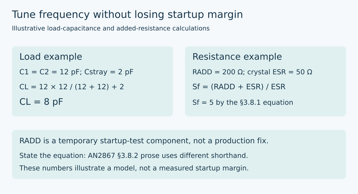
The usual equal-capacitor arrangement does not present the sum of the two external capacitors to the crystal. In AN2867’s model, effective load capacitance is C1 × C2 / (C1 + C2), plus stray capacitance. The parasitic contribution belongs in the calculation; it is not an optional manufacturing footnote.
Consider two hypothetical 12 pF capacitors and an effective stray contribution of 2 pF. The calculated load is 6 + 2, or 8 pF. Replacing both capacitors with 18 pF raises it to 9 + 2, or 11 pF. These are nominal model results, not measured capacitance on a gateway board. Actual pin, trace, and component contributions must be established for the implemented layout.
If the crystal was specified for an 8 pF load, the first nominal result matches that condition and the second does not. That observation alone does not establish which oscillator starts reliably. Frequency tuning and startup qualification answer different questions, and both must be satisfied. Do not select whichever capacitance produces the prettiest frequency-counter reading and assume the rest follows.
Use the correct transconductance interpretation
AN2867 distinguishes a datasheet specification for oscillator transconductance from one for maximum critical crystal transconductance. They are not interchangeable labels. Record which parameter the selected MCU supplies before applying a margin rule. Applying an extra factor to the wrong parameter, or omitting it from the other, can produce a misleading component-selection worksheet.
The note’s equal-load model makes critical transconductance proportional to ESR, frequency squared, and the square of the sum of crystal shunt capacitance and load capacitance. That relationship exposes why “more capacitance” is not a free improvement. It increases the requirement in this model, all other terms held constant.
For a sensitivity illustration, hold frequency, ESR, and shunt capacitance fixed, with hypothetical shunt capacitance of 2 pF. Increasing modeled load from 8 pF to 11 pF multiplies the squared-capacitance term by (2 + 11)²/(2 + 8)², or 1.69. This is a 69% increase in that calculated requirement, not a prediction of startup time or proof that a particular MCU fails. Use the manufacturer’s complete assumptions when converting that sensitivity into a part-selection decision.
Add loss temporarily to expose hidden margin
The series-resistance experiment inserts a temporary resistor in the crystal branch and increases its value while repeating startup attempts. Its purpose is to determine how much additional loss the circuit can tolerate before startup fails. It is not a recommendation to leave the test resistor in the production design.
Distinguish starting from continuing to oscillate. Allowing an oscillator to start first and then changing resistance tests a different condition. Follow a controlled restart procedure, include the specified supply and oscillator configuration, and record the criterion for successful startup. A software timeout must be long enough to represent the intended requirement rather than accidentally redefining the measurement.
The result should be bracketed by tested resistor values, not reported as a fictitiously exact threshold. If one added resistance starts repeatedly and the next does not, retain both values, their tolerances, and the number of trials. A single successful boot does not establish the edge of a distribution, particularly when the failure being investigated is intermittent.
State which resistance equation you used
Revision 24 contains wording that deserves explicit care. Section 3.8.1 defines safety factor using (RADD + crystal ESR) / crystal ESR. Section 3.8.2 describes the startup-blocking added resistance itself as the negative resistance. Do not silently switch between those descriptions in a test report.
Using the equation printed in section 3.8.1, a hypothetical RADD of 200 Ω and crystal ESR of 50 Ω give a safety factor of (200 + 50)/50 = 5. The added-resistor-to-ESR ratio alone is 4. Neither value is a measured result here. Label the added resistance, ESR basis, and selected equation separately so another engineer can reproduce the arithmetic. Resolve the applicable interpretation with the component vendor before using an ambiguous boundary as a release decision.
Section 3.8.3 separately gives HSE and LSE criteria. Do not generalize one oscillator’s threshold to the other or call this factor a regulatory safety certification. It is an oscillator design-margin concept within the manufacturer’s stated scope.
Preserve the actual startup conditions
The useful experiment fixes the board revision, crystal part, capacitor population, oscillator-drive setting, supply behavior, temperature, and startup-detection method. Change one controlled factor at a time before combining the required operating corners. An external reset that leaves an oscillator running is not equivalent to a fresh oscillator start; establish what the chosen reset sequence actually does.
Avoid loading a sensitive oscillator node with an unsuitable probe. Prefer a documented buffered clock observation when available, while verifying that it represents the oscillator of interest. If direct probing is necessary, account for its capacitance and follow the manufacturer’s measurement guidance. A probe that helps the circuit start has changed the experiment.
Release evidence should connect two independent outcomes: acceptable frequency behavior with the selected load, and adequate startup robustness under the required conditions. Preserve the raw attempts and configuration rather than just a successful waveform. The goal is a reproducible operating margin, not a capacitor substitution justified by one convenient boot.
Primary reference and trend scope
STMicroelectronics AN2867, Revision 24, February 2026, sections 3.3–3.4 and 3.8, pages 12–14 and 18–19. Numerical examples are illustrative calculations; no oscillator was measured or qualified for this article.
The preserved Google Trends RISING row “industrial iot solutions,+110%,” worldwide, all categories, web search, July 19–October 19, 2026 supports the industrial-gateway parent topic only. It is not evidence of rising demand for crystal-startup testing or this title.