Gateway Differential Measurements: Budget Common-Mode Leakage Before Trusting a Small Spike
A short spike on a gateway’s differential interface may be real, or it may be common-mode motion leaking through the measurement chain. A differential probe does not make that ambiguity disappear automatically. Before redesigning the board around a small captured disturbance, estimate whether the probe can distinguish it from the much larger voltage shared by both inputs.
The reference is Tektronix’s P7313 Z-Active Differential Probe Technical Reference, document 071-1704-03. Its discussion on printed pages 10–11 defines common-mode rejection and explains a practical residual check. The concepts below apply broadly, but the instrument-specific limits must come from the probe actually being used. No P7313 performance value is being assigned to another probe, and none of the numerical examples is a measurement.
Convert rejection into an input-referred error
Common-mode rejection ratio, or CMRR, compares differential gain with common-mode gain. If a measurement is calibrated in differential input volts, a common-mode component can appear as an equivalent input error of approximately its amplitude divided by the linear CMRR. The corresponding amplitude ratio is 10^(CMRRdB/20).
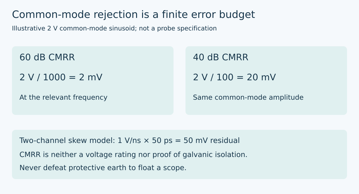
For a hypothetical probe with 60 dB CMRR at the frequency of interest, the ratio is 1000. A 2 V common-mode sinusoid can therefore correspond to 2 mV of input-referred residual. At 40 dB, the ratio is only 100 and the same common-mode amplitude corresponds to 20 mV. These examples assume a linear response, compatible amplitude conventions, and operation within the probe’s allowed ranges.
If the suspected differential disturbance is 5 mV, a possible 20 mV residual makes a confident attribution impossible from that trace alone. Conversely, a favorable 2 mV estimate does not prove a 5 mV spike is real: noise, bandwidth, probe loading, and source imbalance remain. Treat the estimate as one uncertainty term rather than an automatic subtraction from the waveform.
Use the frequency of the unwanted motion
Tektronix notes that CMRR generally decreases with frequency. A DC rejection figure cannot establish rejection of a fast common-mode transient. Nor is the interface’s nominal bit rate a complete description of that transient: edge shape determines the frequency content that reaches the probe.
For a sinusoidal disturbance, compare the CMRR at that sinusoid’s frequency. For a non-sinusoidal event, a single scalar taken from an unrelated point on a curve is insufficient. The frequency-dependent gain and phase influence the time-domain residual. Preserve the full response information available from the instrument manufacturer, and avoid converting a graph into an unsupported guaranteed worst-case value.
This distinction changes the test plan. A slow common-mode sweep checks a different limitation from a fast switching edge, even when both have the same peak voltage. State which disturbance the measurement needs to resolve before deciding whether the selected probe is adequate.
Two scope channels introduce a different mismatch problem
Subtracting two single-ended channels can be useful on suitable low-voltage, safely referenced circuits, but subtraction does not erase channel mismatch. If both channels see the same ramp and one arrives slightly later, their difference contains a transient even when the physical differential input is zero.
In a small-skew approximation, residual voltage is slope multiplied by time skew. An illustrative 1 V/ns common-mode ramp and 50 ps relative skew produce about 50 mV of apparent difference while the ramp is present. Reducing skew to 5 ps reduces that term to about 5 mV. These are mathematical examples, not specifications for an oscilloscope or a promise that deskew removes all error.
A relative gain mismatch creates another residual. In an idealized case, 0.5% mismatch applied to a shared 2 V level corresponds to 10 mV. Deskew does not correct that gain error, while a gain correction does not necessarily align the channels’ frequency responses. Record both channels’ probes, attenuation, bandwidth settings, and compensation rather than treating the arithmetic subtraction as a precision differential instrument.
Check residual pickup without declaring it calibrated
Tektronix describes connecting both differential inputs to the same circuit point as a quick way to assess common-mode residual when the waveform is not sinusoidal. Since the intended differential input is then zero, the remaining capture can reveal whether common-mode error is large enough to matter. The manual explicitly cautions that this is not necessarily an accurate measurement of that error.
Use this only at a suitable point within all instrument and circuit limits, with an approved connection method. Keep the input connection geometry balanced; unequal lead paths and source impedances can reduce rejection. Moving both tips to one point also changes loading and geometry, so do not blindly subtract that capture from a different two-node measurement.
For a gateway debugging record, retain the original capture, the residual-check capture, and the exact connection photographs. A comparable residual is evidence to improve the measurement before changing the product. A small residual supports further investigation but does not independently prove the original spike’s source.
Keep voltage safety separate from rejection
CMRR is not a permissible-voltage rating and does not establish galvanic isolation. Check maximum voltage to ground, common-mode operating range, differential range, transient limits, and applicable measurement-category ratings for the complete setup. A small difference between two nodes can coexist with unsafe absolute potentials.
Never defeat the oscilloscope’s protective earth to obtain a floating measurement. Use appropriately rated differential or isolated equipment and the site’s approved procedure where required. An analytical error budget cannot make an electrically unsuitable setup acceptable.
The final engineering decision should name the smallest disturbance that matters, the accompanying common-mode waveform, and the measurement uncertainty supporting that distinction. Only then can a waveform justify changing termination, filtering, or layout rather than merely changing the instrument connection.
Primary reference and trend scope
Tektronix P7313 Technical Reference, 071-1704-03, printed pages 3–4 and 10–11. All residual, skew, and gain-mismatch numbers above are illustrative calculations, not probe qualification results.
The preserved Google Trends RISING row “industrial iot solutions,+110%,” worldwide, all categories, web search, July 19–October 19, 2026 supports the gateway parent topic only, not a claim of rising searches for differential probes or this title.