IO-Link Class B Ports: Keep Actuator Power Separate from Communication Power
An IO-Link actuator disappears from the gateway exactly when its load supply is switched off. It is tempting to investigate device discovery, cyclic data mapping, or a controller timeout. Before changing software, check whether the installation has preserved the two power domains that make a Class B port useful. An actuator losing its ability to move is not supposed to imply that its communication electronics must lose power too.
This article uses IO-Link Interface and System Specification Version 1.1.4, June 2024, sections 5.4.1–5.4.3, Figure 25 and Tables 11–13. It develops an installation review method, not a claim of tested equipment or functional-safety approval. Numerical examples below are hypothetical engineering calculations.
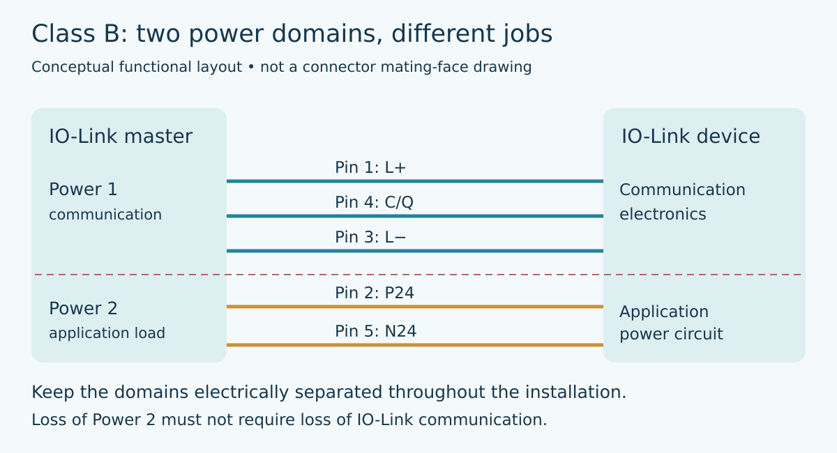
The extra two conductors have a specific job
In the Class B arrangement, Power 1 uses L+ and L− while C/Q carries communication. The additional Power 2 circuit uses P24 and N24. On the five-pin M12 connection, these extra supply conductors occupy pins 2 and 5. The specification requires electrical separation between the supply domains and continued correct communication when Power 2 fails. It also warns that an installation violating that separation at one device can affect other ports.
That is a stronger design requirement than merely fitting a five-pin connector. A cable can have the expected number of contacts and still be the wrong interconnect. Likewise, a terminal board can look orderly while a jumper joins the two return paths. Treat the connector, cable, distribution terminals, device internals, and attached application wiring as one circuit. The intended separation has to survive the complete installed path, not just the master schematic.
Do not generalize Class A accessories into this path. The pin functions are not interchangeable simply because both products use an A-coded M12 connector. Obtain the actual master, device, and accessory pin assignments before building the harness. Connector coding prevents some mistakes; it does not replace that comparison.
Review power removal as a circuit change
Start with a drawing that names each power domain separately. Mark which supply feeds device communication and which feeds the application load. Trace each positive conductor and its matching return all the way to the endpoint. Include shields, mounting connections, service adapters, and external application interfaces where their documentation shows an electrical connection. Do not assume that every visible metal connection is a power return, or that an unknown internal connection is isolated.
Next, mark the exact contacts opened by the installation’s actuator-power switch. If that operation also interrupts Power 1, a communication outage may simply be the predictable result of the selected wiring. If Power 1 remains present but communication still stops, investigate cross-domain paths, device behavior, and switching disturbance before treating the controller as the origin of the fault.
This exercise does not establish a safe machine state. Removing application power can have consequences that depend on the actuator, stored energy, and machinery design. Keep the electrical communication check separate from any safety validation and follow the equipment’s authorized commissioning procedure.
Cable loss belongs to the actuator circuit too
The extra supply deserves its own voltage-drop calculation. Assume an illustrative installation supplies 24.0 V to Power 2 and has 0.80 Ω of total outward-and-return resistance, including the chosen cable and contacts. At a steady application current of 1.50 A, the calculated loss is 1.50 × 0.80 = 1.20 V. The endpoint receives 22.80 V before supply tolerance and other unmodeled losses.
Now assume a hypothetical startup pulse of 3.00 A through the same resistance. The resistive drop becomes 2.40 V and the endpoint becomes 21.60 V. Those values are not permission to run that current through an arbitrary port or connector. Compare the entire waveform against the actual product ratings, current limiting, connector suitability, temperature derating, and device startup requirements. A satisfactory steady-state calculation cannot approve an unsupported pulse.
The two examples explain why a load can behave differently after replacing a short commissioning lead with the final cable. They also show why measuring the cabinet supply alone is incomplete. Record voltage at the relevant endpoint and return pair during the problematic event. A reading referred to the other power domain can conceal the quantity the actuator actually sees.
Make the bench check reveal the distinction
With machinery disconnected or otherwise made safe under its commissioning procedure, establish normal communication using the intended master, device, and cable. Record the configured port type, device identification, and both power-domain voltages. Confirm what the device’s documentation says should happen when application power is absent; an application diagnostic and a missing communication link are different observations.
Then remove only Power 2 through the approved test arrangement. Observe whether communication continues and whether the expected application-power condition becomes visible. Restore Power 2 and record the application’s documented recovery behavior. Repeat with representative cable resistance and the permitted load conditions rather than immediately increasing current to a generic standard limit.
For a troublesome switching event, capture the supply domains and communication symptom against a common time reference. A gateway log alone cannot tell whether a voltage disturbance preceded the link loss. Conversely, a clean-looking slow multimeter reading cannot rule out a short transient. Select the measurement method for the duration of the event and the isolation requirements of the setup. Connecting grounded instruments carelessly can create the very cross-domain connection being investigated.
Hand over a wiring contract, not just a port number
The installation record should identify the master port class, device pin assignment, cable part and conductor arrangement, supply-domain drawing, load envelope, and expected response to removal of Power 2. Attach the actual product limits used for the calculations. If an accessory changes later, repeat the pin and isolation review instead of relying on its connector appearance.
For an industrial gateway project, the valuable outcome is a clear diagnostic boundary: communication power remains a separate circuit from actuator power, and a load-power event is interpreted using evidence from both. That boundary helps the software team distinguish a useful device diagnostic from an avoidable wiring outage without inventing retries to hide the latter.