STM32G474 Parallel ADC Accuracy: Review the Clock-and-Trigger Plan Against the Erratum
A five-ADC STM32G474 design needs more than five valid single-ADC configurations. ST documents a condition in which conversions on one instance can affect another instance's accuracy, and the permitted clock-and-trigger arrangements need to be reviewed as a group.
The released baseline examined here is ES0430 Rev 9, section 2.7.11. As read on 19 October 2026, ST's official preliminary errata updates also lists a June 2026 expected update to that section, with a linked condition table. The page was updated on 12 October 2026. The preliminary table and the released PDF are different documentation states; this article does not present the table as a newly released ES0430 revision.
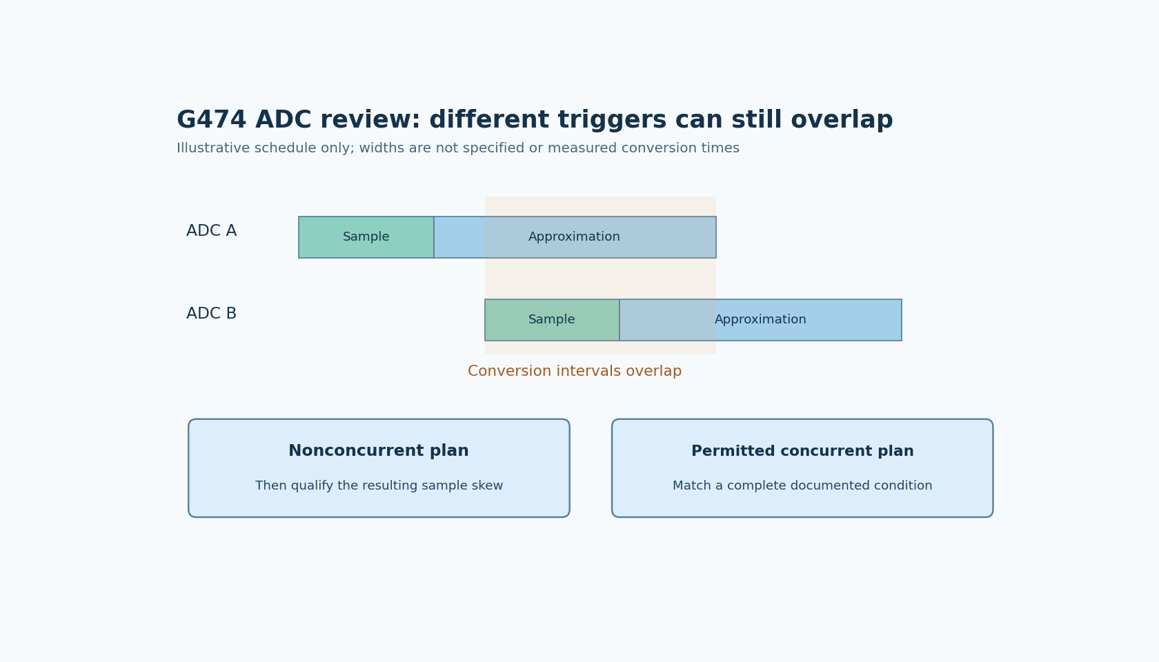
Draw conversion intervals, not just trigger instants
The released erratum defines conversion as including both the sampling phase and the successive-approximation phase. Consequently, triggers that occur at different instants can still produce overlapping conversions.
For each active instance, record its clock source, prescaler, resolution, sampling configuration, trigger source and regular or injected sequence. Use the ADC description in RM0440 Rev 9 to establish the actual sequence and timing configuration.
Then identify groups that can overlap. Include injected conversions and mode changes that occur outside the ordinary periodic path. Reviewing only the nominal steady-state trigger schedule can miss an asynchronous diagnostic conversion that creates a new concurrent group.
Choose a complete documented condition
The linked preliminary update separates nonconcurrent operation from permitted concurrent hardware-trigger arrangements. Its concurrent rows specify combinations of instances, mode, clock source and prescaler, with an additional trigger-clock footnote where applicable.
Use one complete applicable row as the design condition. A statement such as “all ADCs use the same clock” is not a sufficient transcription of a row that also constrains mode, division and triggering.
For a specific preliminary-table example, condition 7 covers ADC1 through ADC5 in normal mode, using synchronous clocks from the same source and the same ADC prescaler. With ADC division by two, its footnote requires the hardware-trigger source clock prescaler to be a multiple of two, such as two, four or six. Merely selecting the same ADC clock while leaving an arbitrary trigger prescaler does not establish that condition. This example is limited to that preliminary row; it is not permission for every other mode or concurrent grouping.
Keep the exact selected row or released-document condition with the design review. Because the preliminary information can change, retain its retrieval date and recheck it before a release or a later clock-tree change. Where a production decision depends on interpretation of preliminary conditions, obtain clarification through the normal vendor-support process rather than inventing a broader guarantee.
Serializing conversions changes the measurement requirement
Avoiding concurrent conversions is one documented approach. That can simplify the interference condition, but it changes when different physical signals are observed.
For a slow monitoring task, sequential samples may be acceptable. For a control or measurement calculation that assumes simultaneous observations, the resulting sample skew can be part of the error budget. Eliminating one hardware condition does not establish that the revised measurement meets its original requirement.
A proposed schedule should therefore show both the absence of forbidden overlap and the maximum permitted inter-channel timing difference. Include scheduling jitter or trigger variation where the chosen implementation introduces it. Do not claim simultaneity merely because all results are later delivered in the same DMA buffer.
The alternative is a supported concurrent arrangement with all of its conditions preserved. The correct choice depends on the application's timing requirement, not simply on which configuration is easier to generate.
Build an acceptance test that isolates the interaction
For later board qualification, hold one input and its local ADC configuration constant while introducing the other instance's conversion activity. Compare the isolated and concurrent cases under the selected clock-and-trigger plan. This is a proposed experiment, not a measured error characterization.
Use appropriate signal sources and observation methods, and retain raw codes before averaging or application compensation. Repeating the test with changed clocks, sequence lengths or injected activity can expose assumptions that were missing from the original schedule.
A clean result on one board does not remove the documented limitation or qualify untested combinations. Conversely, a changed code distribution is not automatically proof of this erratum: input settling, reference behavior, board coupling and other error sources still need distinction.
Make the clock plan a maintained design constraint
The reviewed artifact should list the actual part and silicon revision, applicable errata, active ADC groups and the selected permitted operating condition. Associate it with the clock tree and trigger configuration used by the firmware.
Changes to prescalers, trigger timers or acquisition scheduling should reopen that review. The erratum is not resolved merely because each ADC remains below its individual maximum clock frequency.
No silicon test or accuracy guarantee is supplied here. The practical result is a group-level qualification question: do all overlapping conversions satisfy the exact documented clock-and-trigger condition, and does that condition still meet the product's sample-timing requirement?