Clock Stretching on I2C: Separate a Slow Peripheral from a Controller Timeout
A low SCL interval can be a permitted peripheral wait or an expired host limit. Establish both contracts: how the selected device signals “not ready,” and whether the controller actually observes SCL and waits long enough. A valid sensor behavior and a valid controller implementation can still be incompatible when their timing policies differ.
Applicability: the device example is Sensirion SHT3x-DIS single-shot acquisition, datasheet version 7, December 2022. The concrete host implementation is Linux v6.12 i2c-gpio with i2c-algo-bit. Other controllers, bridges, and sensor modes need independent checks. This article qualifies intentional stretching; recovery from a permanently stuck line is a separate task.
1. Identify whether the chosen command permits stretching
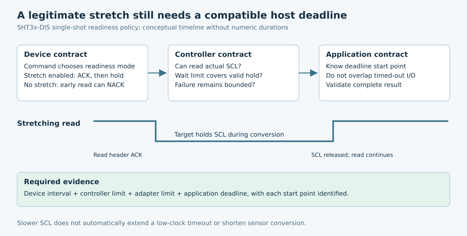
The SHT3x-DIS datasheet provides single-shot commands with clock stretching enabled or disabled. With stretching enabled, the sensor can acknowledge the read header and hold SCL low until measurement completes. With stretching disabled, an early read receives NACK instead. These are different readiness protocols, not two error names for the same transaction.
Record the exact command, repeatability setting, required command spacing, and specified measurement-duration conditions. Do not identify a command only as “read temperature.” A change in operating mode can change the expected response before data is available, even though the sensor and connector remain identical.
For a hypothetical environmental monitor, choose one supported single-shot configuration and document two acceptable designs: a stretching-capable host that waits, or a no-stretch command with a bounded wait/readiness policy. Neither design should treat a normal busy indication as a reason to reset the sensor.
2. Find every timeout along the host path
Build a worksheet with separate entries for the peripheral’s maximum relevant measurement interval, controller stretch limit, adapter transaction timeout, bridge transport timeout, driver retry budget, and application deadline. Record units and what starts each timer. A timer beginning when a request enters a queue is not equivalent to one beginning when SCL is released.
Also record whether each limit is configurable, fixed in hardware, or implemented in software. An application timeout setting cannot enlarge a controller’s hard low-clock timeout. Conversely, an application may give up while a lower layer continues the transfer, so a timeout return must not trigger a competing command while the old operation still owns the bus.
Use the actual operating conditions and device limits. A few successful room-temperature observations establish neither the worst-case stretch nor compatibility across the supported product range. Include documented margins and measurement uncertainty rather than selecting a limit barely above the longest trace seen once.
3. Verify that the host can observe SCL
The Linux v6.12 i2c-gpio driver installs an SCL readback callback only when SCL is not configured as output-only. Its diagnostic message explicitly identifies output-only operation as lacking clock stretching. A nominally open-drain output is not sufficient if the software path never checks whether the physical line rose.
The corresponding i2c-algo-bit implementation releases SCL, checks the input when available, and waits subject to its configured timeout. Inspect this exact path and resolved configuration rather than copying a timeout from a different hardware adapter.
For a hardware controller, make the equivalent review against its reference manual, driver, and errata. Include any level shifter or bus buffer that affects what the host observes. Do not infer support from the connector being labelled I2C or from the controller’s ability to communicate with a device that never stretches.
4. Capture the interval the timeout actually covers
Capture SDA and SCL together with a low-overhead software event marking request submission and completion. For the stretching test, identify the read-header ACK, the interval during which the target holds SCL low, the physical release, resumed clock edges, and the API completion or error.
Measure the low interval at the device and, where buffering exists, at the host side too. Separate the controller’s intentional clock-low period from the additional target hold. A waveform of SCL alone may show the total low interval without establishing which device drove each portion; correlate it with the protocol and a controlled fixture.
Compare the capture with the worksheet. A timeout consistently occurring before legitimate conversion completion suggests a compatibility problem. A timeout after a low interval exceeding the specified device behavior suggests another fault. A trace that resumes correctly while the application reports failure points toward an upper-layer deadline or completion-handling issue.
5. Choose a compatibility change with a bounded outcome
If the controller supports stretching and its limit can safely cover the selected device behavior, configure and qualify that limit. Keep an upper bound so a failed sensor cannot block a shared bus indefinitely. Review the effect on other users of the bus and on the application’s responsiveness.
If the host cannot support the required stretching, the SHT3x no-stretch single-shot command offers a different protocol. Wait according to the documented measurement requirements or retry the documented busy response within a bounded budget. Preserve the required command spacing and check the returned data integrity. Avoid repeatedly restarting a measurement while waiting for the first one to finish.
Simply reducing the bus frequency is not a general repair. It changes clocked transfer time but does not necessarily change the target’s conversion time or the host’s low-clock limit. It can make a test pass for incidental reasons without resolving the underlying contract. State the predicted effect of each change before testing it.
6. Test both legitimate waiting and failure
- Normal readiness: read after completion and verify the full result and integrity fields.
- Legitimate early read: exercise the selected stretching or no-stretch behavior and confirm it is handled without unnecessary reset.
- Near-limit hold: on a suitable test fixture, vary a controlled low interval around the host limit. Confirm where the driver reports failure.
- Persistent hold: verify bounded failure and ownership release through the supported recovery path.
- Concurrent traffic: confirm that another device’s deadlines remain acceptable while the slow target is waiting.
Use isolated test hardware for fault injection and preserve the original command/capture pair. Do not claim that a clamp test reproduces every real sensor failure. After an error, prove the next transaction starts from a defined driver and device state rather than overlapping unfinished work.
The release artifact is the device/host timing worksheet, resolved host configuration, captures covering readiness and timeout boundaries, and the chosen failure policy. No sensor conversion, controller timeout, or fault injection was executed for this article. The proposed method establishes what must be measured and checked before claiming compatibility.