I2C Pull-Up Changes: Use Rise-Time and Sink-Current Evidence Together
A smaller I2C pull-up resistor improves a passive RC rise time while increasing the current every low-driving device must sink. Select a resistance interval that satisfies both constraints, including tolerances, and then verify it on the populated bus. A cleaner rising edge alone is not sufficient evidence that the change is safe.
Applicability: this method covers a passive pull-up, approximately lumped-capacitance I2C segment. TI SLVA689A supplies the calculation model, and TMP102 datasheet SBOS397I supplies one concrete target’s digital-output limits. Active rise-time accelerators, current-source pull-ups, complex level shifters, and long transmission-line behavior need a different model.
1. Draw the actual pull-up network
Inventory pull-ups on the host, every module, switch branch, and test fixture. Parallel resistors reduce the effective resistance even when no individual board has been modified. Record which rails feed them, their tolerances, and which combinations of modules can be connected simultaneously.
Treat SDA and SCL separately. Different devices drive them, and their capacitances may differ. Include connector, trace, input-pin, cable, and probe loading in the estimate. A target that only sinks SDA during ACK still has to meet the low-level requirement at that moment; checking only the host’s driven low is incomplete.
Before measuring resistance, isolate and de-energize the segment through the approved hardware procedure. Powered resistance measurements and uncertain industrial ground connections are inappropriate. During powered waveform checks, use a probe and ground arrangement suitable for the circuit and include their loading in the interpretation.
2. Establish the upper resistance bound from rise time
TI’s I2C pull-up calculation note derives the passive RC approximation tr = 0.8473 × R × C for the 30%–70% transition interval. The corresponding upper resistance is tr(max)/(0.8473 × C). Use the rise-time limit for the actual bus mode and the largest credible segment capacitance.
Do not mix a scope’s default 10%–90% rise-time measurement with a 30%–70% specification. Configure consistent thresholds or calculate from the raw trace. Document the pull-up rail used to define those thresholds. A misleading measurement convention can make an apparently slow bus look compliant, or vice versa.
If capacitance is inferred from a measured edge and known resistance, state the simple-RC assumption. A kinked rise through a level shifter or accelerator does not necessarily represent one capacitor. Compare measurements at the host and the farthest relevant target before accepting that model.
3. Establish the lower bound from every low-driving device
The conventional sink constraint uses the pull-up voltage, permitted low voltage, and guaranteed sink current under the datasheet’s stated conditions. Choose the most restrictive participant, including the controller and any buffer. Absolute-maximum current ratings are not a substitute for a guaranteed logic-low operating point.
The TMP102 datasheet lists an SDA low-level limit of 0.4 V at 3 mA when its supply exceeds 2 V, and its application guidance says pull-up current must not exceed 3 mA. Those conditions belong in the worksheet. They are not a universal I2C sink capability for every attached part.
For a conservative current-cap check, use the highest pull-up voltage divided by the lowest possible effective resistance, assuming a near-zero low voltage. This can be stricter than the familiar calculation that subtracts an allowed VOL. Then check actual low voltage and receiver thresholds separately. The design must satisfy both current and logic-level margins.
4. Work one explicitly hypothetical interval
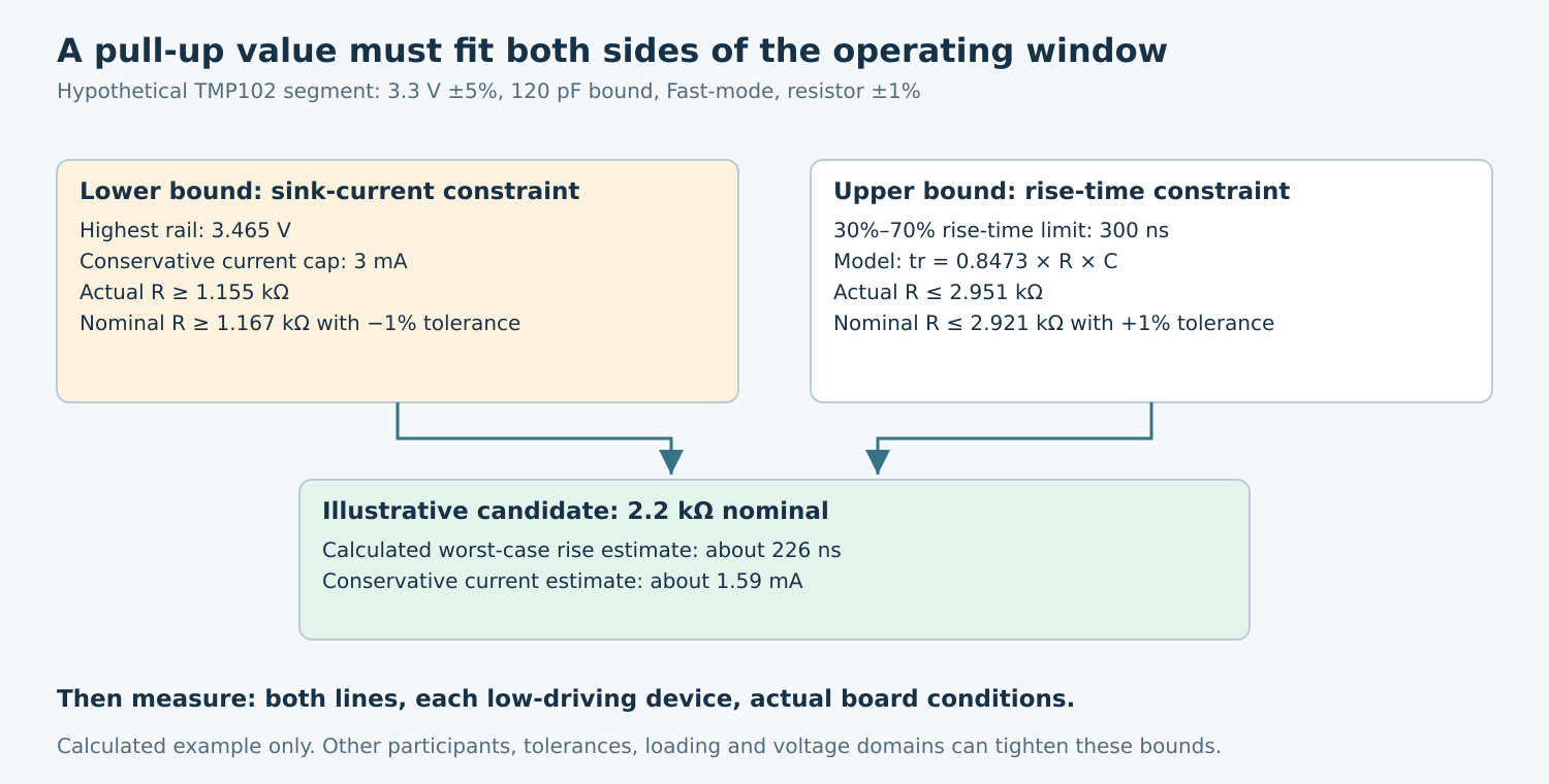
Assume a proposed TMP102 segment uses a 3.3 V pull-up rail with ±5% tolerance, a worst-case estimated capacitance of 120 pF, Fast-mode’s 300 ns rise-time limit, and ±1% resistors. Assume every other participant has been independently checked to tolerate at least the same sink requirement. These are example inputs, not measurements from an Obeita board.
The maximum supply is 3.465 V. Applying a conservative 3 mA current cap requires the actual resistance to be at least 1.155 kΩ. With a −1% resistor tolerance, the nominal value must be at least approximately 1.167 kΩ. The rise-time constraint gives an actual upper value of approximately 2.951 kΩ, or a nominal upper value of approximately 2.921 kΩ after +1% tolerance.
A nominal 2.2 kΩ candidate falls inside this illustrative interval. At the maximum resistance and capacitance, the model predicts about 226 ns rise time. At minimum resistance and maximum supply, the conservative sink-current estimate is about 1.59 mA. These are calculated hypotheses for a test candidate, not recommended universal resistor values or validated electrical performance.
If the lower and upper bounds do not overlap, there is no valid resistor within the assumed model. Consider reducing capacitance, changing the supported bus rate, isolating segments, or selecting suitable buffering. Do not choose whichever bound seems more important and silently abandon the other requirement.
5. Measure the conditions that can invalidate the calculation
After an approved hardware change on a test unit, capture rise time and low voltage for both lines at the relevant locations. Specifically capture target-driven ACK and read-data lows, not only controller-generated bits. Confirm the actual supply and effective pull-up population used in the test.
Repeat across the product’s permitted module combinations and relevant supply/temperature conditions. Record instrument uncertainty and probe loading. If removing a probe changes reliability, investigate that influence rather than reporting only the favorable capture.
Look for incomplete rises, ringing, long low plateaus, voltage-domain clamping, and changed behavior when a module is unpowered. These observations may reveal that the passive single-segment model is inadequate. Stronger pull-ups cannot repair unsupported power-off behavior or every level-shifter limitation.
6. Make the release decision from a worksheet and captures
The worksheet should list bus mode, pull-up rail range, effective resistance range, capacitance basis, required rise time, every participant’s sink/threshold conditions, and the resulting feasible interval. Attach before-and-after raw traces and identify which device was driving each important low.
Accept the change only when the observed electrical margins and transaction behavior meet the defined requirements. Preserve a repeatable workload and error accounting, but do not replace the electrical checks with “no errors seen.” A short successful exchange cannot demonstrate worst-case sink capability or capacitance margin.
No resistor was changed and no waveform was measured for this article. The arithmetic above was calculated from expressly hypothetical inputs and checked source limits. The next engineering step is to populate the worksheet with the actual board, verify its model, and qualify the selected component values under the required operating conditions.