SPI Three-Wire Turnaround: Release the Shared Data Line Before the Device Drives It
A three-wire SPI read requires the host to stop driving the shared data conductor before the peripheral sends its response. Sending zero-valued “dummy” bytes is not equivalent to releasing the output. Qualify the device mode, controller direction switching, and board signal path together, then inspect the command-to-response handover at the target pins.
Applicability: the concrete peripheral is STMicroelectronics LIS3DH, datasheet DocID17530 Revision 2. Linux v6.12 SPI core, spi-gpio, and bitbang implementation provide specific host-side examples. Three-wire terminology varies across products; here it means CS, clock, and one bidirectional data line, excluding power and ground. No board timing or electrical measurement is claimed.
1. Establish which pin changes direction
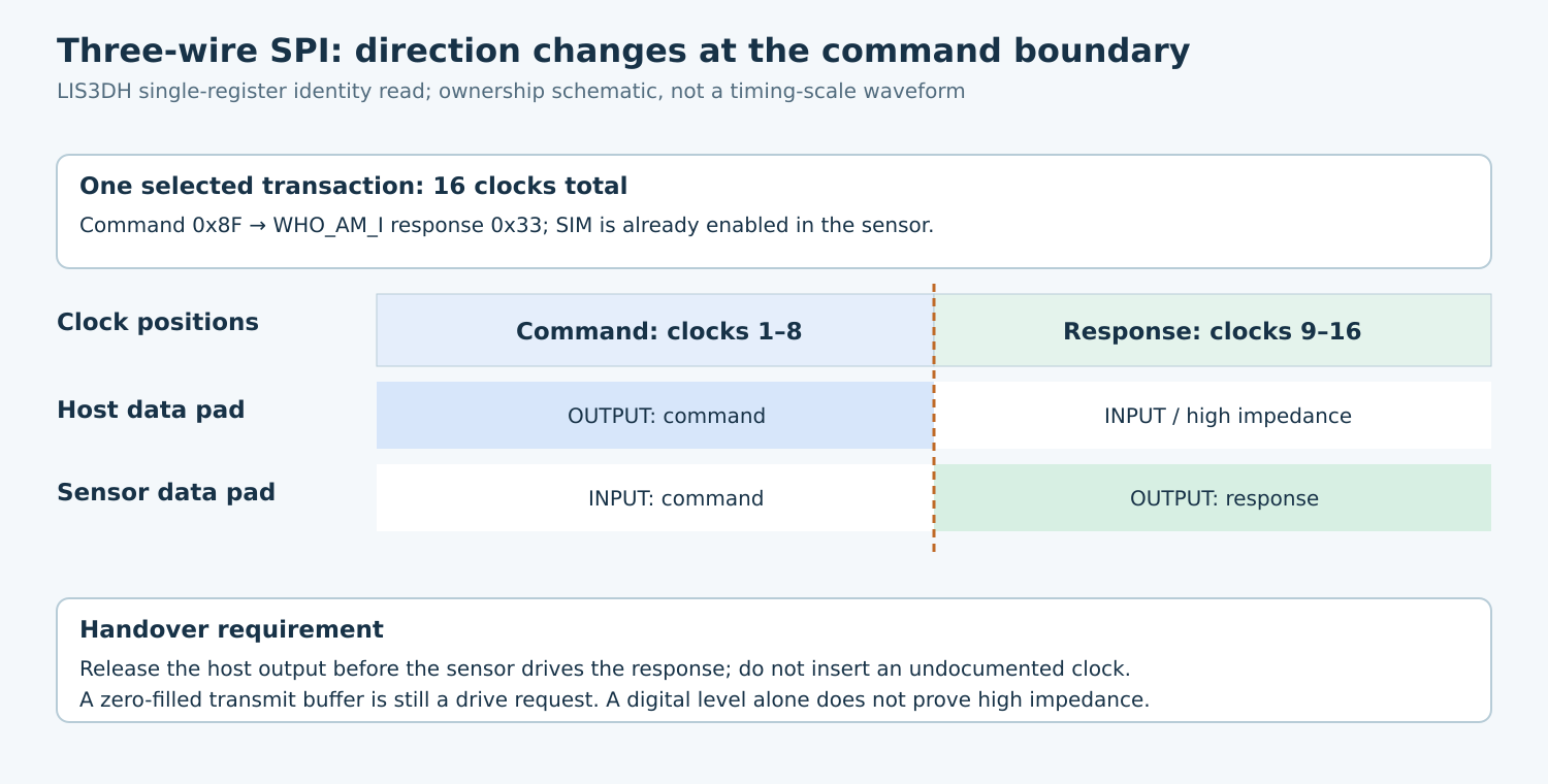
The LIS3DH datasheet assigns three-wire output to its shared SDA/SDI/SDO pad. Setting SIM in CTRL_REG4 at address 0x23 selects three-wire SPI. Its single-register read uses eight command clocks followed by eight response clocks, with the most significant data bit first.
Draw the actual conductor through connectors, level translators, and host pin multiplexing. Identify which physical pad the host samples during reception. A controller that still samples its separate MISO pad will not receive the response merely because the shared line has a correct waveform.
Do not directly connect two push-pull outputs as a shortcut for unsupported direction control. Any approved adaptation needs a circuit-level review with the selected parts. A series resistor is not a general substitute for correct ownership, and this article supplies no universal resistance value.
2. Verify host support in the deployed implementation
Check both the controller’s advertised mode capabilities and the implementation that switches the output enable. An accepted configuration is necessary evidence but does not prove that the board wiring, pin multiplexing, or external translator follows it.
For a concrete reference, Linux v6.12 spi-gpio advertises SPI_3WIRE. Its direction callback changes the MOSI GPIO to input for three-wire reception, and its input helper reads that same GPIO. The driver also supports SPI_3WIRE_HIZ, which adds a clock cycle at turnaround. These are separate behaviors.
Do not enable an extra turnaround cycle simply because its name sounds protective. The LIS3DH single-read format has sixteen clocks; an inserted cycle can consume a response bit and misalign the byte. Release the driver at the required boundary without inventing an extra protocol clock.
The spi-gpio source also makes clear that its bit-delay macro is empty. Treat it as implementation evidence for direction handling, not a calibrated clock generator or proof that a requested speed produces a particular waveform. Qualify the actual timing on the deployed platform.
3. Represent transmit and receive as separate directions
Use a transmit-only command segment followed by a receive-only response segment in one message with the required continuous selection. In the v6.12 core validation, a SPI_3WIRE transfer with both transmit and receive buffers is rejected. A conventional full-duplex helper is therefore the wrong representation for this link.
The v6.12 bitbang transfer path selects line direction from whether the transfer has a transmit buffer, then suppresses the opposite direction for three-wire operation. For the receive segment, omit the transmit buffer; do not supply a zero-filled buffer and assume its contents mean high impedance.
Keep the message and both buffers valid through completion, and check the returned status before using received data. Selection continuity preserves the device command context, but the central qualification here is electrical ownership during that selected interval.
4. Commission with a documented identity read
The LIS3DH WHO_AM_I register at 0x0F contains 0x33. After selecting the device’s three-wire mode through its documented write path, a single-register read has command 0x8F: read enabled, address increment disabled, address 0x0F. Expect the response during the next eight clocks on the shared conductor.
The datasheet’s SPI description uses idle-high clocking, falling-edge data launch, and rising-edge capture. Configure and inspect those edges explicitly. The identity operation verifies the communication path; it does not validate acceleration accuracy or every register access.
Plan startup so the sensor’s interface selection and the host’s direction behavior agree. A reset that clears the device’s interface setting can invalidate a previously working read path. Preserve the intended configuration in software and restore it through a supported sequence before accepting identity or data reads.
5. Observe ownership, not only decoded bytes
- Mark the command boundary: identify the eighth command capture edge and the first response bit.
- Check host release: inspect the controller’s output-enable behavior or a suitable hardware observation, including any external translator direction.
- Check response sampling: confirm that the host reads the shared pad and that the first and last response bits meet the selected timing requirements.
- Count clocks: distinguish a direction transition from an added clock and verify the complete sixteen-clock identity operation.
- Check completion and deselection: ensure the host does not reacquire the line while the selected peripheral still drives it.
A digital logic trace alone cannot prove high impedance when two outputs happen to drive the same level. Combine source/register evidence with appropriate analog measurements when contention is suspected. Do not deliberately force opposite drive levels on a production board as a routine diagnostic.
At safe operating conditions, compare the raw receive byte with the captured response bits. If the line is correct but the buffer is wrong, inspect host receive routing and sampling. If only the first bit is wrong, inspect handover and added clocks before changing unrelated payload decoding.
6. Qualify transitions and recovery
Repeat the identity read after cold start, sensor reset, controller reinitialization, and supported suspend/resume. Exercise traffic to another target if the bus is shared. Require per-device direction and mode settings to be restored before selection, rather than relying on whichever operation ran last.
Use software fault fixtures to test unsupported modes and incorrectly constructed full-duplex requests without driving conflicting outputs. On real hardware, stop on abnormal waveform or current evidence and investigate the electrical path before increasing clock rate.
No SPI transaction was executed for this article. The release artifact is a shared-line ownership map, exact device/driver versions, checked interface-enable sequence, message-direction specification, and annotated target capture. A correct hexadecimal identity is useful evidence; the handover proof explains why the link remains valid across resets and operating conditions.