STM32H563 GPDMA Allocation: Reserve Large FIFOs and 2D Channels Deliberately
An STM32H563 can have a free DMA channel and still lack a free channel suitable for the next data path. Its GPDMA channels do not all have the same FIFO depth or addressing capability. Allocate the scarce channel classes before assigning convenient channel numbers in individual drivers.
The concrete allocation below uses H563's two eight-channel GPDMA instances and AN5593 Rev 9. It does not apply the newer H5Ex/Fx channel table to H563, and it does not claim measured throughput or a universal channel priority policy.
Normalize the channel numbering first
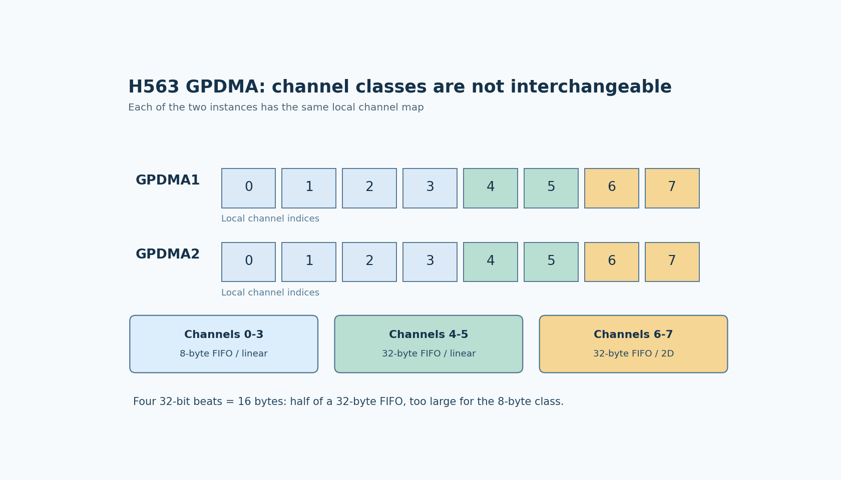
AN5593 sections 2.1 and 2.2 explain a flattened software view: GPDMA1 channels occupy numbers 0–7 and GPDMA2 channels occupy 8–15. Thus a table entry for flattened channel 14 means local channel 6 on GPDMA2.
Keep both representations in the allocation document. A driver using an instance pointer plus local channel index should not receive flattened index 14 as though it were a valid local index. This is a bookkeeping hazard when an application note, generated initialization and runtime allocator use different naming conventions.
The H563 datasheet describes the GPDMA capabilities, while RM0481 supplies the target register and request-routing details. Treat the application-note numbering as a documented view, not a substitute for the selected software API.
Allocate by class, not by count
For the H563 row of AN5593 Table 3:
- Local channels 0–3 on each instance have 8-byte FIFOs and linear addressing.
- Local channels 4–5 have 32-byte FIFOs and linear addressing.
- Local channels 6–7 have 32-byte FIFOs and 2D addressing.
The last group is a subset of the large-FIFO resources. Assigning all four 2D-capable channels to ordinary linear transfers can leave a later stride-based transfer with no suitable resource, despite unused small-FIFO channels elsewhere.
A reasonable allocation order is to identify mandatory 2D requirements first, then high-bandwidth or burst-sensitive paths, then ordinary peripheral transfers. This is an engineering allocation strategy, not a hardware rule that every 2D channel must always remain unused until a 2D request arrives. The real constraint is the simultaneously active workload and its permitted reconfiguration points.
Convert burst settings into bytes
AN5593 states that the maximum DMA burst size a channel can effectively perform is half its FIFO size. Burst length alone is therefore an incomplete configuration: multiply the number of beats by the source or destination data width as applicable.
A four-beat burst of 32-bit words is 16 bytes. It matches the half-FIFO capacity of a 32-byte channel, but exceeds the four-byte half-FIFO capacity of an 8-byte channel. Changing a macro from one beat to four without reviewing the allocated channel class cannot establish the intended transfer behavior.
The note recommends single-word bursts for typical small-FIFO peripheral/SRAM paths and four-word bursts by default for large-FIFO memory-to-memory paths. These recommendations also depend on the actual peripheral's transfer contract. An 8-bit peripheral register does not become a safe 32-bit access merely because wider accesses would use the bus efficiently.
Treat source and destination as separate sides of the transfer. One side may be a peripheral with specific request and width requirements; the other may be memory. Do not copy one burst setting to both sides without checking each side's documented capability.
Resolve a concrete contention case
Suppose a product has one strided buffer operation, two bulk memory copies and several UART data paths. This is a hypothetical resource mix, not a tested H563 workload. Reserve a 2D-capable channel for the strided operation, consider large linear channels for the copies, and start ordinary UART paths in the small-FIFO class where their requirements permit it.
Now add another strided operation that must overlap the first. The relevant question is how many 2D-capable channels remain during that interval, not whether the total channel count is still below sixteen. If the allocator allows borrowing a 2D channel for a linear task, define when that task releases it and whether the new operation can wait.
Do not solve the conflict by reprogramming an active channel whose descriptors and completion belong to another client. Channel reassignment needs an explicit quiescent boundary and ownership transfer in the software architecture. The resource table identifies the hardware requirement; the driver lifecycle must enforce it.
Qualify the allocation under the real overlap
The useful artifact is a concurrency map listing each operation's instance/local index, FIFO class, required addressing mode, source/destination widths and burst byte counts. Add the intervals in which requests can overlap and the permitted waiting or fallback behavior.
Performance qualification should then use the actual mix, including bus contention and peripheral rates. A successful isolated copy does not establish that a latency-sensitive peripheral remains serviced while bulk transfers run. AN5593's recommendations guide the initial allocation; they do not replace those measurements.
No firmware or workload test was run for this article. Its outcome is a resource-budget method that preserves H563's specialized channels for operations that actually need them and makes burst feasibility visible before performance tuning starts.