STM32G474 Encoder Index: Preserve the Same Reference Position in Both Directions
An encoder index can load zero while moving forward and the auto-reload value while moving backward. On the STM32G474 timer, that difference is intentional: the index logic moves the counter discontinuity to the same physical phase boundary in both directions. Forcing zero on every index rising edge would discard that relationship.
This example uses TIM3 in quadrature encoder mode, with TIM3_ECR.IE enabled and IPOS = 0b11. The behavioral reference is RM0440 Rev 9, section 30.4.18, pages 1340–1342. All sequences below are constructed logic fixtures. No encoder, motor or homing system was operated.
Establish the three input paths
A and B drive the timer’s two encoder inputs; the index Z reaches tim_etr_in. Enabling the index through IE is permitted only in the documented encoder modes. An external interrupt attached to Z does not automatically provide the timer’s phase-qualified index behavior.
For a concrete package reference, the STM32G474RE in LQFP64 exposes PA6 and PA7 for TIM3_CH1 and TIM3_CH2 on AF2, and PB3 for TIM3_ETR on AF10. These selections come from DS12288 Rev 6, pin definitions and Table 13. PB3 also has a debug function, so its actual board allocation matters. This is a pin-function example, not a board wiring approval; electrical levels, filtering and the timer’s ETR source selection still need review.
Fix the A/B polarity and decoding mode before interpreting direction. Swapping A and B changes the directional relationship. Record the observed logical sequence rather than labeling clockwise rotation as inherently increasing for every encoder mounting.
Locate the shared physical boundary
Use the positive quadrature order 00, 01, 11, 10, 00. In the manual’s IPOS = 0b11 case, the qualified index sets the up-counting counter to zero when the encoder enters state 11. Reversing across that same boundary produces 11 -> 01; the down-counting index loads ARR when leaving 11.
For an illustrative ARR = 7, the relevant coordinate pair is therefore:
| Motion across the reference | A/B transition | Counter immediately after the index event |
|---|---|---|
| Up-counting | 01 -> 11 |
0 |
| Down-counting | 11 -> 01 |
7 |
The values identify the neighboring bins on either side of one boundary in an eight-count cyclic coordinate. They do not indicate that the reference moved seven physical counts. The next ordinary down-counting transition continues from seven to six.
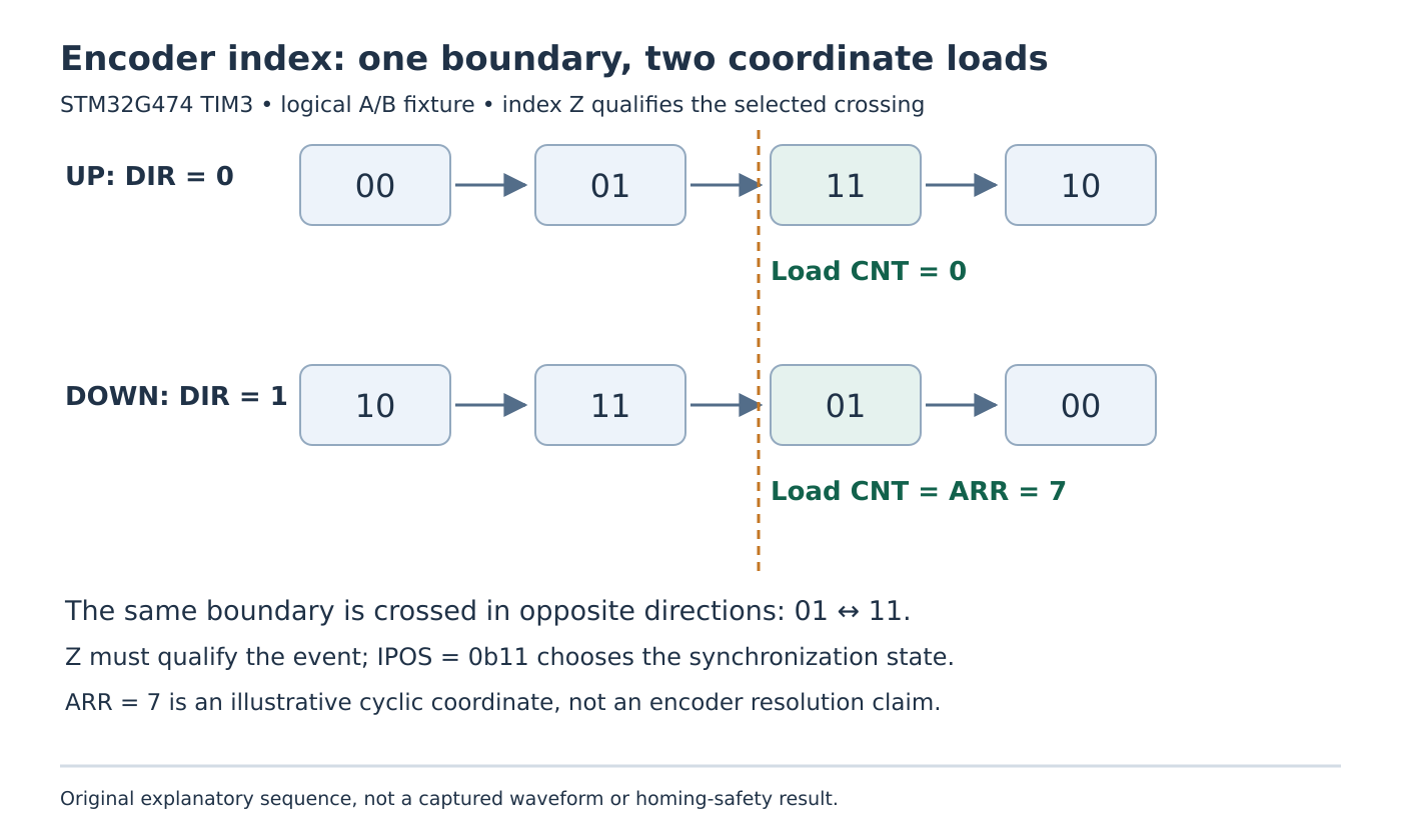
A test that expects identical counter numbers on both sides of the boundary will report a false failure. Compare the transition location, direction and post-event coordinate together. Likewise, observing a Z edge alone is insufficient: synchronization depends on the selected A/B state and the index qualification.
Keep pulse width in the acceptance condition
RM0440 describes index pulses gated by both A and B, gated by either channel, and ungated pulses. The first occupies a quarter of one channel period; the second occupies a half period. The timer accommodates these conditioning options without a separate gating-mode selection, but IPOS must identify the intended encoder state.
For an ungated index, the manual requires the pulse to be strictly shorter than two encoder periods. A width equal to or greater than two periods can reset the counter repeatedly. That is a boundary condition to check with the actual encoder waveform, including jitter, rather than a reason to count all Z transitions as independent revolutions.
Express width relative to the A/B period at the operating speed. A fixed microsecond pulse can span a different number of encoder periods as speed changes. Input filtering also belongs in the selected configuration; do not assume an arbitrary filter preserves every qualifying edge at maximum speed.
Exercise reversal around the boundary
A proposed logic-generator fixture should first establish the positive sequence with Z inactive. Then qualify one index crossing with Z covering the intended state boundary, repeat in reverse, and reverse direction close to that boundary. Retain A, B, Z, direction, counter and index-event observations in the same trace.
Add an ungated pulse safely below the documented width limit and a deliberately overlong pulse in a register model or isolated fixture. The latter should expose why repeated resets are possible; it is not a production operating point.
Acceptance requires agreement between the physical phase boundary and the direction-dependent counter load. The article does not establish mechanical homing repeatability, stopping distance or a safety function. Those require the real encoder, wiring, mechanics and application behavior to be qualified separately.