ESP32-S3 USB Product Design Needs a PHY Map and an Independent Recovery Route
A custom ESP32-S3 USB product can enumerate correctly and still lose its only debugging route as soon as application USB starts. The underlying design question is not whether the board has two USB connectors. It is which controller owns each physical transceiver, how that assignment changes between boot and application execution, and how a technician recovers a build that never starts its USB stack.
This review targets ESP32-S3 and ESP-IDF v5.2.5. It distinguishes the fixed USB Serial/JTAG controller, the USB-OTG controller and the ROM console implementation. It does not apply those peripherals to the original ESP32. The proposed checks have not been executed on hardware.
Separate the controller from the connector
The versioned USB Serial/JTAG guide describes a hardware-fixed serial and JTAG function. It cannot be turned into a custom HID or storage device by replacing descriptors. Application-defined USB functions instead use USB-OTG with an appropriate device stack.
Make a schematic-level map with five fields: connector, D+/D− nets, PHY, controller and intended software owner. A second connector may terminate at a USB-to-UART bridge rather than another native USB transceiver. That bridge can still be a valuable independent service path, but its presence does not create another native USB endpoint resource.
For the internal PHY, identify GPIO20 as D+ and GPIO19 as D−. Check the actual board schematic rather than relying on a development-board label. Record which protection, switching and power circuits sit between connector and chip. The map should make it impossible to approve a feature merely because an unused connector exists.
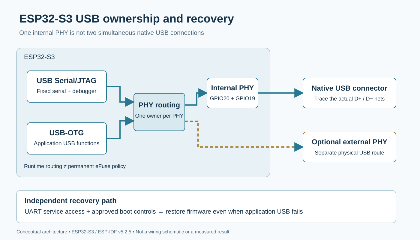
Original architecture diagram. The optional external PHY and service route are design choices, not a validated reference circuit.
Distinguish runtime selection from permanent boot policy
The v5.2.5 USB PHY driver allocates a selected PHY and rejects a second allocation when that PHY is already in use. Its target and controller fields describe separate choices. The ESP32-S3 low-level implementation explicitly enables software control of the internal-PHY selection when configuring USB-OTG.
This matters because an application selecting OTG at runtime is not the same operation as changing an eFuse. The ROM USB-OTG console guide discusses the default routing and a permanent USB_PHY_SEL change. Do not turn that ROM-console instruction into a blanket requirement to burn an eFuse before every TinyUSB application.
Review boot, download mode, normal application and diagnostic mode separately. For each mode, write down the expected routing and which initializer establishes it. Treat simultaneous use of the two controllers as a hardware allocation problem: retaining both physical links requires an appropriate external-PHY arrangement, not two software handles aimed at the same internal PHY.
Keep the three serial implementations distinct
“USB CDC console” can refer to the Serial/JTAG controller’s serial function, the ROM USB-OTG console, or an application TinyUSB CDC function. They differ in initialization, descriptors and failure behavior. The ROM-console guide explicitly excludes combining that console feature with TinyUSB; TinyUSB can provide its own CDC function instead.
Name the selected implementation in the product configuration and troubleshooting instructions. Capture its expected USB identity before and after application startup. If the host reports a disappearing port followed by a different identity, investigate whether this is an intended controller or descriptor transition before diagnosing signal integrity.
For managed USB components, retain the dependency lockfile alongside the IDF version and sdkconfig. Pinning ESP-IDF alone does not identify every separately resolved component. Do not copy configuration structures from a newer esp_tinyusb release into this baseline without reviewing the component’s actual interface.
Make recovery independent of successful enumeration
A proposed service requirement is simple: a deliberately broken application USB configuration must not prevent an authorized technician from restoring an approved image. Choose the recovery path before enclosure design removes access to boot straps and reset.
The Serial/JTAG guide describes manual download entry using GPIO0 low during reset when application pin reconfiguration has removed the device. Preserve an electrically appropriate way to perform the chosen recovery sequence. If UART service access is the independent route, document its connector, voltage domain, boot controls and supported flashing workflow. Do not confuse a port that prints after application startup with a route that works before the application runs.
Security provisioning changes this assessment. The v5.2.5 USB device guide warns that Secure Boot or flash encryption disables the ROM USB-OTG stack’s serial-emulation and DFU update routes. Requalify recovery with the intended production security configuration; a development-board demonstration is not evidence for the provisioned product. This is not a recommendation to disable security or alter irreversible eFuses.
Qualify the complete transition rather than one successful flash
Use a recoverable development fixture and retain a known-good image. First record enumeration in download mode, then during normal application startup, and finally after a deliberately invalid application descriptor configuration. Observe the independent route throughout. Restore the approved image using the documented service procedure and confirm that normal operation returns.
Repeat the relevant transitions with the release build and production-equivalent security settings on a designated test unit. Record host OS, board revision, controller routing, component versions, recovery steps and whether each failure was intentional. Stop when the expected route is absent; do not improvise an eFuse change to make a test pass.
The release artifact should be a PHY ownership map, a mode-by-mode USB identity record and a proven recovery procedure. No enumeration, flashing, security provisioning or recovery test was performed for this article. Its contribution is the architecture and acceptance boundary that those tests must establish.