Gateway Junction Temperature: Use Psi-JT Without Mistaking It for Thermal Resistance
A warm gateway processor does not reveal its junction temperature merely because a thermal camera reports the package surface temperature. The missing step is choosing a parameter whose definition matches the measurement. Confusing junction-to-top characterization with a junction-to-case resistance can turn a carefully measured surface temperature into a misleading silicon-temperature estimate.
The preserved Google Trends export for July 19–October 19, 2026 lists “industrial iot solutions” as RISING at +110%, worldwide, all categories, web search. This supports the parent industrial integration topic, not a claim of rising demand for this specific thermal technique.
Define the measurement before choosing a number
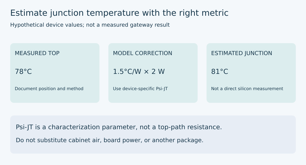
Texas Instruments distinguishes three relevant quantities in SPRA953D. Junction-to-ambient resistance depends on the package, board and environment. Junction-to-case resistance is characterized with heat directed through a specified case surface. Psi-JT instead relates the junction-to-top temperature difference to total device dissipation while heat follows multiple paths. It is a characterization parameter, not a resistance representing all heat crossing the top. The application note gives the estimation relationship TJ = TT + Psi-JT × P and cautions that board construction and airflow affect Psi-JT. These distinctions are documented in sections 1, 2 and 3.
For a gateway review, start with a one-line measurement statement: “Estimate the operating junction temperature of device U7, in this package, from its top surface under a specified workload.” That statement rules out several tempting substitutes. Cabinet temperature is not package-top temperature. Total gateway input power is not U7 dissipation. A coefficient from a similarly named part in a different package is not automatically transferable.
The first deliverable should therefore be a parameter identity record, not a temperature result. Record the exact ordering code, package suffix, datasheet revision, coefficient name, coefficient value and stated characterization conditions. If the datasheet does not provide a suitable parameter, leave that field unresolved and seek a supported measurement or modeling route. An empty field is more useful than a plausible but untraceable number.
Calculate a transparent example
Consider an explicitly hypothetical device with a measured top temperature of 78°C, estimated device dissipation of 2 W and a package-specific Psi-JT of 1.5°C/W. The indicated estimate is 78 + 1.5 × 2 = 81°C. These values illustrate arithmetic; they are not measured gateway performance or specifications for a particular processor.
Now suppose someone replaces Psi-JT with an 8°C/W junction-to-case value and obtains 94°C. The difference is not a reason to average the answers. It is a reason to inspect their definitions. The second calculation assumes a heat-flow relationship that has not been established for this assembly. A conservative-looking mistake can still lead the team toward the wrong corrective action or obscure a measurement problem.
A useful review worksheet keeps the measured quantity and calculated quantity in different columns. Put 78°C beside “package top, measured” and 81°C beside “junction, estimated using the stated model.” Do not label both as measured temperatures. That small distinction prevents downstream test reports from acquiring more certainty than the experiment provides.
Bound dissipation without counting the whole gateway
Build a power inventory around the target device. If several rails feed the processor, record each rail’s voltage and current under the same operating state. Determine whether the measured electrical input is dissipated inside the device or transferred elsewhere. For example, power delivered to an external load should not automatically be counted as internal heat. State any subtraction or approximation rather than hiding it inside a spreadsheet cell.
A low-voltage bench setup can compare two reproducible software states: a communication-heavy workload and a defined idle state. Keep peripheral configuration, enclosure orientation and neighboring loads unchanged. Record timestamps so power observations and temperature observations refer to the same condition. Do not combine a brief peak-current reading with a stabilized temperature without explaining what the combination represents.
If the dissipation estimate spans 1.8–2.2 W, the same illustrative coefficient gives a model correction of 2.7–3.3°C. This narrow arithmetic interval does not include uncertainty in Psi-JT or top-temperature measurement. Listing those uncertainties separately makes clear which improvement would actually help. More current-meter digits will not repair an unsuitable thermal model.
Keep the sensor from changing the experiment
TI’s section 3.1 recommends fine thermocouple wire, attention to attachment and wire routing, and emissivity correction for infrared measurements. The underlying practical issue is that the measurement arrangement can perturb the surface being measured.
Photograph the sensing position and document the attachment method before closing the enclosure. Repeat the installation on another sample or repeat the same installation after removal if reproducibility matters. A reading that changes substantially when the wire routing changes deserves investigation before it becomes a release limit.
Treat enclosure access as an experimental variable. Measuring with the lid removed may change the condition you intended to qualify. If a feedthrough is needed, record its size and placement, and assess whether it alters airflow or a designed thermal contact. Work only on appropriate low-voltage hardware and maintain the product’s normal electrical protections.
Decide what the result can support
Compare the estimate, with an explicitly chosen uncertainty allowance, against the operating junction-temperature limit for the exact device. An absolute-maximum rating is not a recommended target. If margin is small, improve the evidence before declaring success: validate the measurement technique, obtain manufacturer guidance for the actual package, or use a more representative thermal model.
Changing to a lid-coupled heat spreader is not merely a way to subtract degrees from the old estimate. It changes the heat paths and can invalidate an earlier coefficient assumption. Revisit the model after that mechanical change. Likewise, a firmware workload change belongs in the thermal configuration record if it materially changes device dissipation.
The finished engineering artifact is a traceable temperature estimate: a named device, a matching parameter, a documented top measurement, a bounded dissipation estimate and an explicit applicability statement. That is much more actionable than a single impressive thermal image or a calculation that treats every °C/W entry as interchangeable.
Primary reference
- Texas Instruments, Semiconductor and IC Package Thermal Metrics, SPRA953D, revised March 2024: sections 1–3, pages 2–10; equation 8 on page 8 and measurement guidance on page 9. Numerical examples and the review worksheet above are original illustrative engineering analysis, not manufacturer test results.