Gateway Buck Input Filters: Damping the Source Impedance, Not Just the Ripple
A gateway can acquire a cleaner-looking input-current spectrum and a worse power rail after an LC filter is added. The missing check is the interaction between the filter’s output impedance and the converter’s input behavior. Treating a regulated converter as a fixed resistor hides the mechanism that makes this possible.
This article considers an isolated, current-limited low-voltage DC bench setup, not mains wiring. Texas Instruments application note SNVA538, originally published by National Semiconductor in 2010, provides the source/filter impedance criterion and parallel-damping architecture. The numerical example below is an original idealized calculation, not a simulation or measurement of a particular regulator.
Start with a constant-power approximation
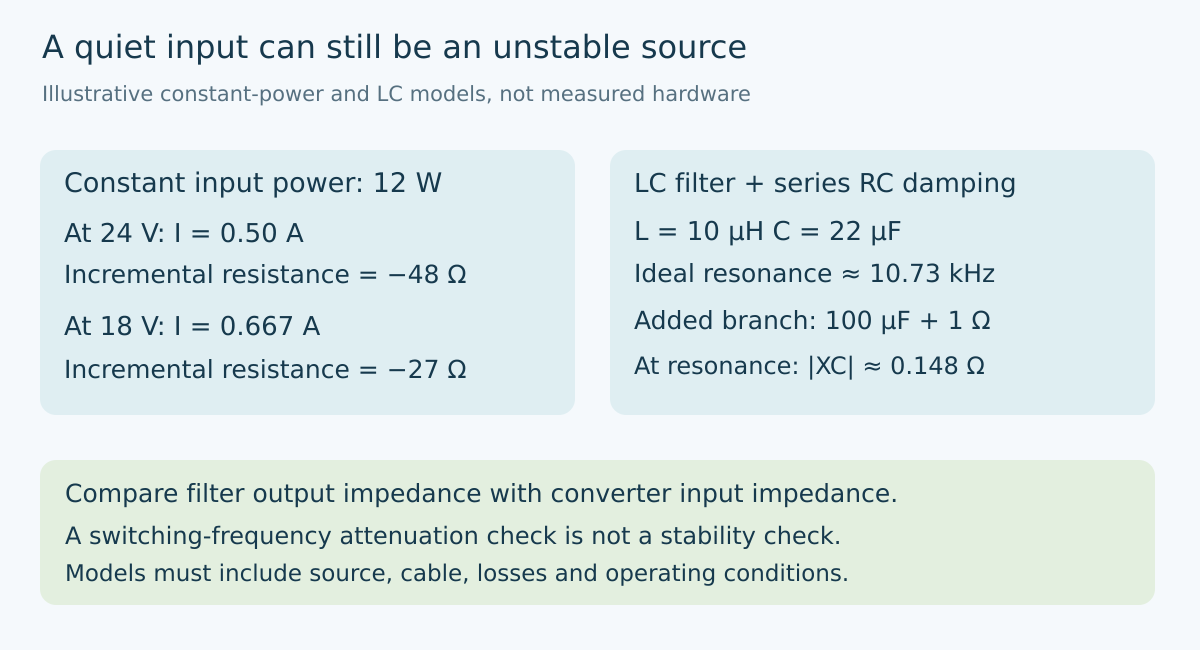
Suppose a hypothetical gateway consumes 12 W from a 24 V input. Over a frequency range where its regulator maintains approximately constant input power, current is P/V. Its operating current is therefore 0.50 A. A small voltage reduction requires a current increase rather than a decrease.
Differentiating I = P/V gives dI/dV = −P/V². The corresponding incremental resistance is dV/dI = −V²/P, or −48 Ω at this operating point. The ordinary ratio V/I is positive 48 Ω, but it is not the small-signal resistance. Substituting the positive ratio in a filter-stability model reverses the relevant behavior.
At 18 V and the same assumed input power, current rises to approximately 0.667 A and the incremental resistance becomes −27 Ω. The reduced magnitude makes a given source impedance more significant. This is one reason a filter review should include the low end of the supported supply range instead of only the nominal input.
The approximation has boundaries. Converter bandwidth, efficiency variation, input capacitance, current limiting and discontinuous operation all change the actual frequency-dependent input impedance. A negative resistance calculated at DC is not a complete impedance plot and cannot establish stability by itself.
Locate the resonance before increasing capacitance
Consider a hypothetical 10 µH series inductor followed by 22 µF effective shunt capacitance. Their ideal resonant frequency is 1/(2π√LC), approximately 10.73 kHz. The characteristic impedance √(L/C) is about 0.674 Ω.
Neither number is the peak output impedance of the real filter. That peak also depends on winding resistance, capacitor losses, source impedance and any deliberate damping. Two filters with identical inductance and capacitance can have very different resonant peaks. The value printed on the capacitor does not establish its effective capacitance at the operating voltage, either.
To calculate filter output impedance, set the ideal source’s small-signal voltage to zero and look back into the filter from the converter terminals. For a simple model with series resistance R and inductance L feeding capacitance C, the impedance is the parallel combination of R + jωL and 1/(jωC). This is a different quantity from the filter’s forward voltage attenuation.
A filter can attenuate switching-frequency ripple while presenting an undesirable impedance peak at a much lower frequency. A good attenuation result at one frequency therefore does not close the stability question.
Give resonant energy somewhere to go
SNVA538 explains that keeping filter output impedance well below converter input impedance reduces interaction with the converter control loop. It also describes a series resistor-capacitor damping branch connected in parallel with the main filter capacitor. The extra capacitor prevents the damping resistor from becoming a continuous DC load while allowing it to dissipate AC energy.
For an illustrative branch containing 100 µF and 1 Ω in series, the capacitor’s reactance magnitude at 10.73 kHz is approximately 0.148 Ω. The branch is therefore predominantly resistive near the nominal resonance. At 100 Hz its capacitive reactance is approximately 15.9 Ω, making it a much weaker load there.
These values demonstrate the frequency-selective damping idea; they are not a recommended bill of materials. The added branch changes the complete network, and its capacitor still has bias, temperature and ripple-current constraints. Resistor dissipation must come from the actual AC waveform or a justified model, not from the input voltage divided by its resistance.
Do not confuse this branch with a resistor inserted in the gateway’s entire DC supply path. The latter carries average input current and creates continuous voltage loss. Either topology requires its own calculation rather than a shared label such as “damping resistor.”
Compare impedances under the same conditions
Build a frequency-domain model that includes the intended source, cable, protection components and effective component values. Evaluate the filter seen at the converter pins rather than at a remote power connector. Compare its output impedance with the converter input impedance at corresponding supply and load conditions.
A magnitude separation is a useful conservative screening approach, not a universal proof for every control architecture. When curves approach or cross, phase and the combined loop behavior matter. Use the selected regulator’s documented stability guidance and an appropriate impedance or loop analysis instead of declaring failure or success from a single crossover point.
Keep the distinction between model and experiment visible. A proposed verification can compare an unfiltered supply, the initial filter and a deliberately damped filter while holding converter load and wiring constant. Measure input voltage at the regulator as well as output voltage. Use suitable low-voltage equipment, short measurement returns and current limiting; do not defeat existing protection to obtain a cleaner trace.
Release the filter as part of the power system
Record the source configuration, cable assumptions, input-power range, effective capacitances, inductance under bias and damping-component tolerances. Retain the impedance plots and the conditions behind them. Include load transitions and supply changes in the later hardware qualification because a quiet steady-state waveform does not establish a robust operating envelope.
The engineering decision is not whether LC filtering is good or bad. It is whether this filter and this regulated load remain compatible. Ripple attenuation describes what noise is removed; source impedance explains whether the filter also changes the converter’s ability to regulate.
Primary reference
The preserved Google Trends RISING row “industrial iot solutions,+110%,” worldwide, all categories, web search, July 19–October 19, 2026 supports the parent integration topic only. It does not establish search growth for this electrical mechanism or article title.