Gateway MLCC Flex Cracks: Move the Strain, Not Just the Capacitor
A gateway can pass board-level electrical testing and fail after it is screwed into its enclosure. If a ceramic capacitor is damaged during assembly, replacing it without changing the mechanical load path may reproduce the same failure. The useful investigation is not simply “which capacitor failed?” It is “which operation bent the board at that capacitor?”
The preserved Google Trends export for July 19–October 19, 2026 lists “industrial iot solutions” as RISING at +110%, worldwide, all categories, web search. This is parent-topic evidence, not measured growth for capacitor failures or a particular assembly technique.
Treat the assembly drawing as part of the circuit
Murata’s public mounting guidance identifies board bending as a source of capacitor damage. Its mounting-position section addresses orientation, board-separation locations and screw holes; its assembly guidance recommends supporting the board during insertion of other components. These are mechanical concerns rather than a substitute for electrical rating checks. The exact capacitor’s approved specification still governs its use.
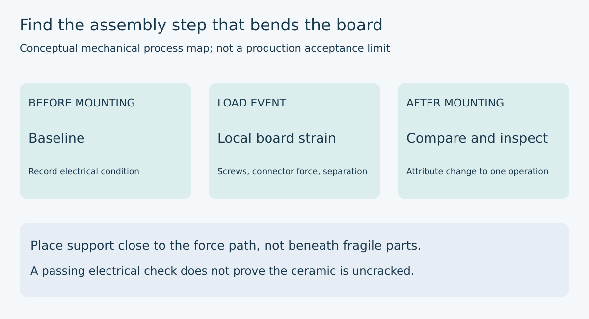
Start an investigation with a marked photograph of the complete gateway board. Identify ceramic capacitors, mounting holes, panel tabs, board connectors, clips and any enclosure feature that contacts the board. Mark where an operator or fixture applies force. A connector at the board edge may be mechanically important even when the failed component is several centimeters away.
Now draw the support points separately from the force points. The distinction matters: a board can be fastened securely in its final state yet bend substantially while the first fastener is installed. Similarly, a test fixture may hold the perimeter but leave a connector insertion point unsupported. The assembled product drawing alone can miss these intermediate configurations.
Build an event sequence rather than a fault story
Create checkpoints before depanelization, after depanelization, after connector installation and after enclosure fastening, where those operations exist. Preserve board identity through the sequence. Record the electrical test outcome at each checkpoint, but do not equate an electrical pass with proof that the ceramic is mechanically undamaged.
For a returned unit, avoid inventing the missing history. Record the observed condition and obtain manufacturing records if available. “Failed after shipment” does not establish that shipping caused the crack. Earlier assembly damage, later handling and unrelated electrical faults remain separate hypotheses until evidence narrows them.
A practical experiment changes one operation at a time on representative, appropriately authorized engineering samples. Compare the present support arrangement with a revised fixture while holding the board revision, connector and assembly sequence constant. Record actual applied force or a reproducible process setting where suitable instrumentation exists. Do not describe an operator’s impression of “gentle pressure” as a controlled load.
Understand what orientation can and cannot solve
Murata’s layout article, revised July 27, 2022, explains that capacitor orientation relative to board stress and separation lines affects susceptibility to cracking. It also discusses local slits as a way to reduce transmitted strain. Those examples are conditional layouts, not permission to cut arbitrary slots into a gateway board.
Translate the guidance into your board’s actual bending geometry. Define the capacitor’s long axis, the separation line and the expected deflection direction explicitly on the drawing. A phrase such as “rotate the capacitor ninety degrees” is incomplete without those references. If the board is bent by multiple operations in different directions, an orientation that helps one step may not address another.
Moving the component may be preferable to rotating it when the original location sits beside a screw or an unsupported connector. However, check the electrical consequences of the move. A decoupling capacitor cannot be relocated indefinitely without revisiting its connection to the device it serves. Mechanical and electrical constraints should appear on the same review sheet rather than being traded through undocumented layout edits.
Follow the force into the support
Suppose a connector requires downward insertion force near the center of a board, while the fixture supports only the corners. The proposed engineering change is to support the board near that force path with a correctly placed fixture feature. It is not to press the board harder against its corners or place a support against a fragile underside component.
Document the proposed support contact area and verify component clearance on the opposite side. Consider height tolerance: a support that is too high may preload the board before the connector is touched. A support that is too low may engage only after substantial bending. The fixture needs an inspection method and maintenance responsibility, not merely a nominal CAD height.
For enclosure assembly, inspect the relationship among standoffs, board flatness and the fastening sequence. A misaligned hole should not be corrected by pulling the board into position with a screw. Use the mechanical design’s specified fastener process; this article provides no universal torque or allowable board-strain limit. Those limits must come from the relevant product and process qualification.
Separate detection from prevention
Electrical screening is useful for finding changes, but the prevention question concerns the mechanical process. A proposal that only adds another electrical test may improve sorting without removing the strain source. Conversely, a redesigned fixture should not be declared successful solely because a small sample happens to pass.
Choose inspection and failure-analysis methods with qualified personnel and the component supplier as appropriate. Preserve suspect samples before rework destroys evidence. Record whether damage was directly observed, inferred from electrical behavior or merely suspected. Do not mix those evidence levels in a report headed “confirmed flex cracks.”
A useful engineering report contains the original load-path sketch, the operation associated with the change, the revised support or layout, and the verification conditions. It also states the sample scope and what remains unproven. That record makes the finding transferable to the next enclosure or connector revision without pretending that one experiment establishes lifetime reliability.
The objective is to keep assembly strain away from a brittle component while preserving its circuit function. Replacing a capacitor is a repair. Changing the operation that bends the board is a candidate corrective action. A controlled comparison is what distinguishes the two.
Primary references
- Murata, Caution/Notice for ceramic capacitors, public 21-page PDF, accessed October 20, 2026: “Soldering and Mounting,” mounting-position and assembly sections. The retrieved PDF has no clear revision date; retain its snapshot hash rather than assigning one.
- Murata, What kind of layout helps prevent chip multilayer ceramic capacitors from cracking?, final revision July 27, 2022, sections 1–2. Event sequencing and fixture-review procedures above are original proposed engineering work, not reported manufacturer testing.