Reviewing AI-Assisted MCU Drivers: Registers, Timing and Failure Paths
AI-assisted MCU driver work needs a review boundary at the hardware register, not merely at the compiler. A plausible function can use the wrong register semantics, wait forever, or return stale data after a fault. The useful deliverable is a small patch whose assumptions, failure paths and acceptance evidence can be checked against one exact device.
This article presents an invented acquisition peripheral and deliberately constructed examples of flawed and reviewed generated-style code. No AI tool was run for this example, and no hardware test or timing measurement is reported. The snippets are teaching material, not hardware-ready templates.
1. Prepare an input packet that constrains the draft
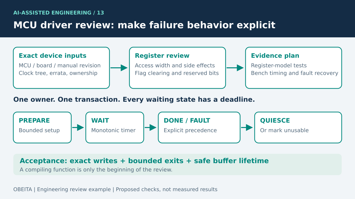
Start with the complete MCU ordering code, silicon revision, board revision, reference-manual revision, errata and the exact SDK or device-header commit. Include the relevant register pages rather than a product-family name alone. Two members of the same family can expose similarly named flags with different clearing rules. A model must not fill that gap by remembering a nearby device.
Add the clock tree actually selected by the board, allowed transfer rates, peripheral reset state, pin mapping and power-mode constraints. State whether the caller runs in a task or interrupt, whether DMA is involved, who owns the peripheral, and how cancellation works. Define success, timeout, hardware fault and invalid-argument results before requesting code. If any input is missing, ask the drafting assistant to list the uncertainty and leave a named placeholder.
A good assignment is narrow: draft a single bounded acquisition transaction using supplied register definitions; identify every manual-derived assumption; do not invent addresses, reset values or errata workarounds. Request a separate uncertainty list and test proposal. Keep licensed reference material and confidential schematics within the project’s approved information-sharing arrangements.
2. Read the flawed draft as a set of claims
/* Invented teaching peripheral: deliberately flawed */
ACQ->STATUS |= DONE;
ACQ->DIV = 48000000 / requested_hz;
ACQ->CTRL |= START;
while (!(ACQ->STATUS & DONE)) { }
return ACQ->DATA;
The first line is the most important review target. Suppose this fictional STATUS register contains write-one-to-clear completion and fault bits. A read-modify-write operation can write back ones for unrelated pending events and clear them. An ordinary RAM-style update is therefore the wrong abstraction. Arm’s CMSIS-SVD register description explicitly distinguishes access properties, modified-write behavior and read side effects. An SVD file is useful review input, but the exact device manual and errata remain necessary.
The literal 48 MHz silently claims that the peripheral clock equals a fixed frequency. The division silently claims a particular divider encoding and rounding rule. Neither claim has been established. A zero request divides by zero; a high request can produce an illegal divider. Even a numerically valid result can exceed the sensor’s allowed clock or violate an acquisition settling time.
The loop has no deadline and no fault branch. A disconnected peripheral, stopped clock or unhandled overrun can hang the caller indefinitely. The function also merges a legitimate data value with every possible error because it has no independent status result. Finally, it assumes no interrupt or second task will acknowledge the same flag. These are behavioral defects even if all names compile correctly.
3. Review the correction before mapping it onto registers
/* Review pseudocode, not a device implementation. */
require(exclusive_owner && output != NULL);
require(valid_clock_and_divider(clock_hz, requested_hz));
require(timer_runs_during_wait && budget_within_wrap_limit);

prepare_idle_device_or_fail();   // bounded, device-specific
ack_owned_stale_flags();        // exact manual-defined write
configure_validated_divider();
start = monotonic_ticks();
start_one_transfer();
for (;;) {
    s = read_non_destructive_status();
    if (s & FAULTS) {
        capture_fault(s);
        return abort_and_quiesce_or_mark_unusable(IO_ERROR);
    }
    if (s & DONE) {
        value = read_result_in_required_order();
        acknowledge_owned_completion();
        *output = value;
        return OK;
    }
    if (elapsed_unsigned(start) >= budget_ticks)
        return abort_and_quiesce_or_mark_unusable(TIMEOUT);
}
The correction intentionally separates policy from device access. Each helper needs a reviewed implementation for the chosen silicon. For the fictional write-one-to-clear register, acknowledging an event means writing only the documented owned mask, without reading it first. That rule cannot be copied onto a read-to-clear register or a device requiring a particular status/data read sequence.
The example assumes a single owner, one outstanding transaction and a non-destructive status read. Faults win over completion when both are observed, because this illustrative API does not allow suspect data to escape as success. Another product may need a different policy; make that choice explicit. A timeout must leave the peripheral idle, or mark it unusable until a bounded reset path succeeds. Returning an error while DMA still writes into a released buffer is not safe recovery.
Use a monotonic time source whose behavior is known in the relevant power and interrupt states. An unsigned elapsed-time calculation can handle counter rollover only within a documented interval and observation model. State the maximum budget and ensure the timer continues advancing. A timeout measured by an interrupt-maintained tick can fail if the polling code prevents that interrupt from running.
4. Review timing, concurrency and error ownership separately
Build a register-access checklist from the manual: access width, alignment, reserved-bit requirements, write protection, reset values, flag-clearing sequence and clock/reset prerequisites. Annotate why each register is touched. Do not add memory barriers merely because they look cautious; use the architecture and device requirements that explain which ordering must be enforced.
For timing, calculate the programmed rate from the selected clock, actual divider encoding and rounding choice. Compare the result with the peripheral’s limits and the application’s permitted error. Include conversion time, chip-select setup/hold where applicable, and the time needed to recover from failure. These are proposed calculations, not measured performance.
For concurrency, choose one owner for transaction state and completion. Check interrupt priority, shared data, cancellation and callback context against the selected RTOS API. A volatile variable is not a complete synchronization design. For DMA, document buffer lifetime, memory accessibility and any platform-specific cache maintenance. Review those obligations even when the draft uses a familiar vendor function name.
5. Turn the review into falsifiable tests
- Register model tests: emulate write-one-to-clear behavior, simultaneous DONE and FAULT, stale completion and reserved bits. Acceptance requires the exact intended writes and no unrelated flag acknowledgment.
- Boundary tests: try zero and out-of-range rates, the smallest and largest legal divider, timer rollover and an unavailable clock. The expected result is a defined rejection or bounded failure without a false success value.
- Ownership tests: inject cancellation and a second caller at each transition. The proposal should demonstrate that a buffer cannot be reused while hardware still owns it, and that completion is delivered at most once.
- Bench tests: on the selected board, capture the relevant clock/data/control signals, repeat cold starts, and exercise the supported supply and temperature conditions. Compare measured timing with pre-agreed limits rather than treating a visible waveform as a pass.
- Recovery tests: remove the peripheral response or inject a supported fault safely. Confirm the timeout status, recovery duration and subsequent transaction behavior, including the explicit unusable state if reset fails.
Record firmware commit, compiler options, board identity, test setup, expected limit, actual observation and raw trace location. Simulations establish software behavior under a model; bench traces establish behavior of the tested assembly under stated conditions. Neither justifies an unrestricted reliability claim.
6. Package the human-reviewed result
The review record should connect each changed register access to its source, each failure branch to a test, and each unresolved assumption to an owner. Keep the original flawed draft if it helps explain the correction, but accept only the reviewed diff. A second AI review can generate useful questions; it cannot certify the first draft through agreement.
For product work, Obeita’s firmware and BSP diagnostics service provides a relevant engineering discussion route. The STM32 data-acquisition project shows related acquisition and application-integration context. That project link does not mean the fictional driver above was used, generated by AI, or tested in that delivery.