Back-Powering Through I/O: Explain Current That Remains After a Rail Is Disabled
A disabled supply can still receive current through a signal connection from an energized domain. Diagnose that path by mapping every crossing signal, observing the supposedly off rail, and removing or changing one supported source at a time. A regulator-disable success and a GPIO configured as input do not establish electrical isolation.
Applicability: this is a board-level partial-power-down procedure. Texas Instruments SN74AXC1T45, datasheet SCES882E revised December 2023, is the concrete example of a translator with documented power-off behavior. The illustrated board topology is hypothetical and has no package pin numbers. No rail measurement or component substitution was performed.
1. Distinguish an off command from an unpowered domain
Record the supply enable command, regulator output, target supply pin voltage, and any remaining supply sources. A rail may stay energized because another legitimate consumer owns it, because stored charge has not discharged, or because an unintended path supplies it. Those possibilities require different fixes.
Measure at the receiving component as well as the regulator when useful. A connector, isolation element, or separate local rail can make their readings differ. Capture the decay and subsequent behavior rather than taking one reading immediately after disable. A slowly falling capacitor voltage is not the same observation as a rail held up indefinitely by an external signal.
Do not impose a universal “off equals zero volts within a millisecond” rule. Define the required voltage and timing from the selected loads, isolators, supply circuitry, and restart requirements. The electrical acceptance condition must be stronger than the name of a software power state.
2. Draw the powered signal sources
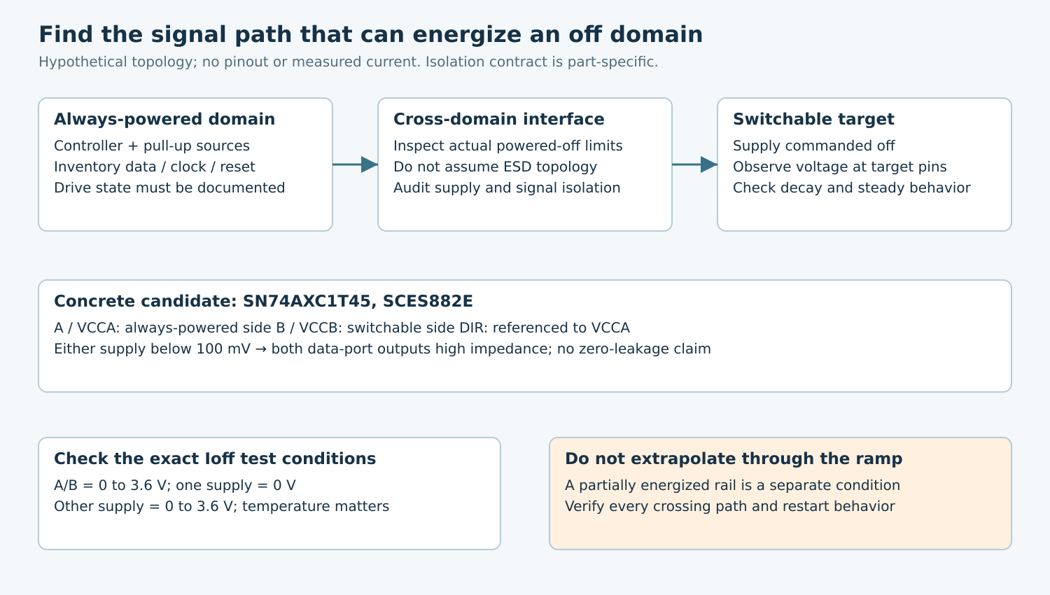
List every path crossing into the disabled domain: clocks, data, interrupts, reset, chip select, debug, analog inputs, and pull-up networks. Mark the supply that drives each signal and each pull resistor. Include paths through translators and switches rather than treating those components as automatically protective.
TI’s SCDA015C powered-off-protection brief explains how an internal I/O-to-supply ESD diode in an unprotected switch can conduct when an input exceeds the unpowered supply. It distinguishes preventing supply back-power from maintaining signal-path isolation. These mechanisms are device-specific; not every input has the same clamp structure.
Use that mechanism as a hypothesis, not a fabricated internal schematic of the unknown receiver. Obtain its actual powered-off input limits and leakage specifications. An absolute-maximum table describes stress limits, not a promise of functional operation or acceptably low shutdown current.
3. Qualify the actual isolation component
The SN74AXC1T45 datasheet gives a concrete bounded contract. If either VCCA or VCCB is below 100 mV, both data-port outputs are disabled into high impedance. DIR is referenced to VCCA. Its Ioff table applies to A/B port voltages from 0 to 3.6 V with one supply at 0 V and the other from 0 to 3.6 V: limits are ±5 µA over −40°C to 85°C, or ±7.5 µA over −40°C to 125°C.
High impedance therefore does not mean zero leakage. Nor may the 0-V Ioff test be silently extended to every partially discharged rail voltage. Record the exact off-state and ramp conditions covered by the chosen part, including its control inputs. A rail hovering above the isolation threshold deserves separate analysis.
For a hypothetical A-to-B connection, assign the always-powered controller to A/VCCA and the switchable target to B/VCCB, with direction established in the A domain. Review the complete datasheet and actual board before using this arrangement. It is a one-bit direction-controlled translator, not a universal replacement for every bidirectional bus or analog isolation problem.
4. Run controlled path-isolation experiments
Use a development fixture with current limiting and accessible measurements, and first verify that every proposed driven/unpowered combination remains within all component ratings. Do not intentionally inject current into an undocumented pin to find its failure threshold.
- Establish the target-off condition with all external signal sources safely disconnected or in documented non-injecting states.
- Reconnect one source group while preserving the same supply sequence and observe target rail voltage and current.
- Where permitted, compare a static low, static high, and representative activity. Record the actual pin voltage, not only the requested GPIO value.
- Repeat with pull-up networks accounted for separately from active drivers.
- Restore normal power and confirm the target’s first functional transaction and configuration.
If a rail rises only when one signal group is present, that narrows the suspected path. It does not yet prove which internal structure conducts. Check whether another connected device, level translator, or test instrument supplies the current. A meter’s input impedance can also affect a weakly energized rail.
5. Choose a fix that survives every owner
A firmware sequence can stop traffic and place supported outputs in non-injecting states before power removal. Verify bootloader, crash, reset, and resume behavior as well as the normal shutdown path. A firmware-only fix that requires a running application cannot cover a cold plug-in event before that application exists.
Where the power topology requires isolation independent of software, choose a component with applicable powered-off specifications and control-domain behavior. Review leakage, signal compatibility, loading, propagation, supply sequence, and temperature limits. A convenient translator footprint is not enough to establish suitability.
A series resistor may limit current, but it does not inherently isolate the rail or guarantee valid logic. Evaluate allowable injection current, resulting rail voltage, signal timing, and component stress before considering it. Likewise, adding a discharge load can conceal back-power by wasting current rather than removing its source.
6. Verify shutdown and restart together
The acceptance matrix should include each domain powered alone, both powered, shutdown in both orders, supported ramp conditions, connected external cables, and firmware reset during the transition. Add a peer-active case when another domain must continue communicating independently.
Record both residual off-state current and the target’s restart behavior. Partial energization can invalidate assumptions about a clean power-on reset even when the board appears to restart. Use the target’s documented reset and power sequence rather than treating a dark indicator as evidence of a complete power cycle.
Deliver the crossing-signal map, exact datasheet conditions, path-isolation observations, and before/after functional checks. The useful result is an explained current path and a qualified off-state contract. A lower total reading without that explanation is insufficient evidence that the domain is safely isolated.