LE Coded PHY Selection: Check Reliability and Airtime Together
Select LE Coded from measured delivery and airtime under the same workload, not from a nominal range multiplier. First prove that the connection uses LE Coded in the intended direction. Then establish which coding scheme the transmitter actually used; requesting S=2 or S=8 does not make that preference a per-packet guarantee.
Applicability: Bluetooth Core 6.1 and Zephyr v4.2.0 connection APIs, with controlled peers supporting the tested PHYs. The airtime example is an unencrypted ACL data packet with a 16-bit header, 27 payload octets and no CTE. All comparison runs are proposed, not performed. No receiver sensitivity, range or current consumption is claimed for an unspecified board.
1. Capture requested and effective modes separately
Record requested transmit PHY, requested receive PHY, coding preference, final transmit PHY and final receive PHY. The HCI LE Set PHY contract allows the controller to retain its current PHY, and a successful update-complete event can report no change. It also permits overriding the preferred transmit coding.
The Zephyr header names BT_CONN_LE_PHY_OPT_CODED_S2 and BT_CONN_LE_PHY_OPT_CODED_S8 as transmit preferences. Its connection PHY information contains separate transmit and receive PHY fields, not a promise that every coded packet uses one fixed S value.
Use a suitable controlled capture or controller diagnostic that exposes actual coding for the packets being compared. In the Link Layer packet format, the Coding Indicator identifies the coding of the second FEC block. If the available evidence establishes only “LE Coded,” report the coding mix as unknown rather than labeling the run S=8.
Qualify both directions. A sensor-to-gateway improvement does not prove the reverse control path uses the same PHY, coding, transmit power or antenna conditions. Keep command acknowledgement success in the experiment if the product needs bidirectional operation.
2. Derive packet duration from the fields
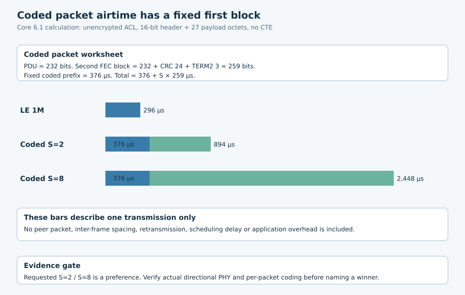
Core 6.1 Table 2.1 gives a fixed 376 microseconds for the coded preamble and first FEC block. The second block contains the PDU, 24-bit CRC and three termination bits. For the stated packet, the PDU is 16+8×27=232 bits, making that second block 259 input bits.
At S=2, duration is 376+2×259=894 microseconds. At S=8, it is 376+8×259=2,448 microseconds. The corresponding LE 1M packet, with the stated unencrypted and no-CTE assumptions, is 80+8×27=296 microseconds.
| Actual packet mode | Calculated one-packet duration |
|---|---|
| LE 1M | 296 µs |
| LE Coded, S=2 | 894 µs |
| LE Coded, S=8 | 2,448 µs |
The coded duration is not simply the complete uncoded packet duration multiplied by two or eight, because the fixed first block differs. These values cover one transmission only. They exclude peer packets, inter-frame spaces, retransmissions, event scheduling and host delay.
For production encryption, account for the MIC in the transmitted PDU length and recalculate. Verify the actual packet length in the trace; application record size is not necessarily Link Layer payload size. Do not disable required product security to preserve the illustrative 27-octet calculation.
3. Define a matched delivery experiment
Use the same sequence-numbered application records, offered cadence, connection parameters, data-length settings and test duration for each mode. Keep the payload small enough for the intended common packetization, then confirm that packetization actually remains comparable.
Fix board revision, enclosure, orientation, supply and supported transmit-power setting. Record both radios’ firmware and antenna configurations. Conducted or shielded attenuation testing can make the link condition more repeatable; a radiated installation test remains necessary for the product’s real antenna and surroundings.
Define success as a unique valid record received before its deadline. Count late records, duplicates and missing records separately. Retain the number generated and admitted for transmission so a smaller sender workload cannot masquerade as better radio delivery.
Do not call application sequence loss “packet error rate.” Link Layer retransmission can conceal radio errors, while application queue drops can create gaps without a failed radio packet. Keep those observations in separate columns and label unavailable radio evidence honestly.
4. Compare airtime paid for useful delivery
Where instrumentation supports it, sum the observed transmission durations, including retransmissions, over the same reporting window. State whether that sum covers one direction or both. Compare it with the number of unique on-time application records.
A mode with longer individual packets may still improve useful delivery under a difficult link, but the result must come from the trace. Conversely, longer transmissions can consume more of the available schedule even when every record arrives. Inspect queue age and missed application deadlines alongside delivery fraction.
Repeat the mode order or interleave controlled runs so changing surroundings do not always favor the last configuration. Use several link conditions, including a strong-link control and the product’s difficult supported condition. Preserve all runs rather than selecting one favorable distance.
The Core physical-layer sensitivity requirements define receiver tests with explicit signal and error conditions. They are not installation-range guarantees. A board datasheet’s sensitivity claim likewise requires its stated conditions; neither turns a PHY choice into a universal distance promise.
5. Make the selection conditional on evidence
| Observation | Decision |
|---|---|
| Requested coded mode was not selected | Resolve capability or controller policy; comparison is inconclusive |
| LE Coded selected but S value unobserved | Report coded-only result; do not claim a coding-specific winner |
| S=2 meets delivery and deadline requirements | Compare its airtime cost with other passing modes |
| S=8 improves delivery but breaks deadline or capacity | Revise workload or reject that operating point |
| No mode meets the requirement | Revisit radio design, environment or product requirement |
If adaptive switching is contemplated, qualify the static operating points first. Then define entry/exit evidence, minimum dwell and an explicit fallback for unsupported changes. Avoid driving a mode change from every noisy RSSI sample without proving the resulting behavior.
6. Preserve a coding-specific acceptance record
Retain requested settings, effective directional PHYs, coding evidence, actual packet lengths, offered records, unique on-time records, retransmission evidence and airtime totals. Add host queue delay and any disconnect reason. The result should distinguish a failed negotiation, an RF delivery issue and a host-side deadline failure.
Rerun after controller firmware, antenna, encryption or payload changes. Accept a PHY policy only for the tested workload and environment, with an identified fallback. The useful conclusion is which supported mode meets the delivery requirement at an acceptable measured airtime cost, not which nominal radio label sounds longest-range.