LVGL Redraw-Area Constraints: Align Invalidated Regions to the Display Controller
Expand dirty rectangles outward before rendering, using the controller’s window granularity and inclusive endpoints. Then prove that the expanded rectangle fits the logical display and that the draw buffer can hold at least one permitted transfer-height unit at the widest possible area. Changing coordinates only inside flush is too late to create missing pixels.
Applicability: LVGL v9.3.0, partial rendering, RGB565, no rotation or display offset in the initial fixture. The controller constraint below is hypothetical: eight-pixel horizontal blocks and four-row vertical blocks, anchored at zero. It is not a specification for a named panel. Verify the actual controller and transport before adopting any numbers. The proposed integration tests have not been executed.
1. Translate the hardware rule into geometry
Obtain the permitted start coordinates, end coordinates, width and height restrictions from the selected controller’s official documentation. Some restrictions apply to address windows; others apply only to a transfer’s byte count. Do not turn a DMA-length requirement into a pixel-window requirement without checking their relationship.
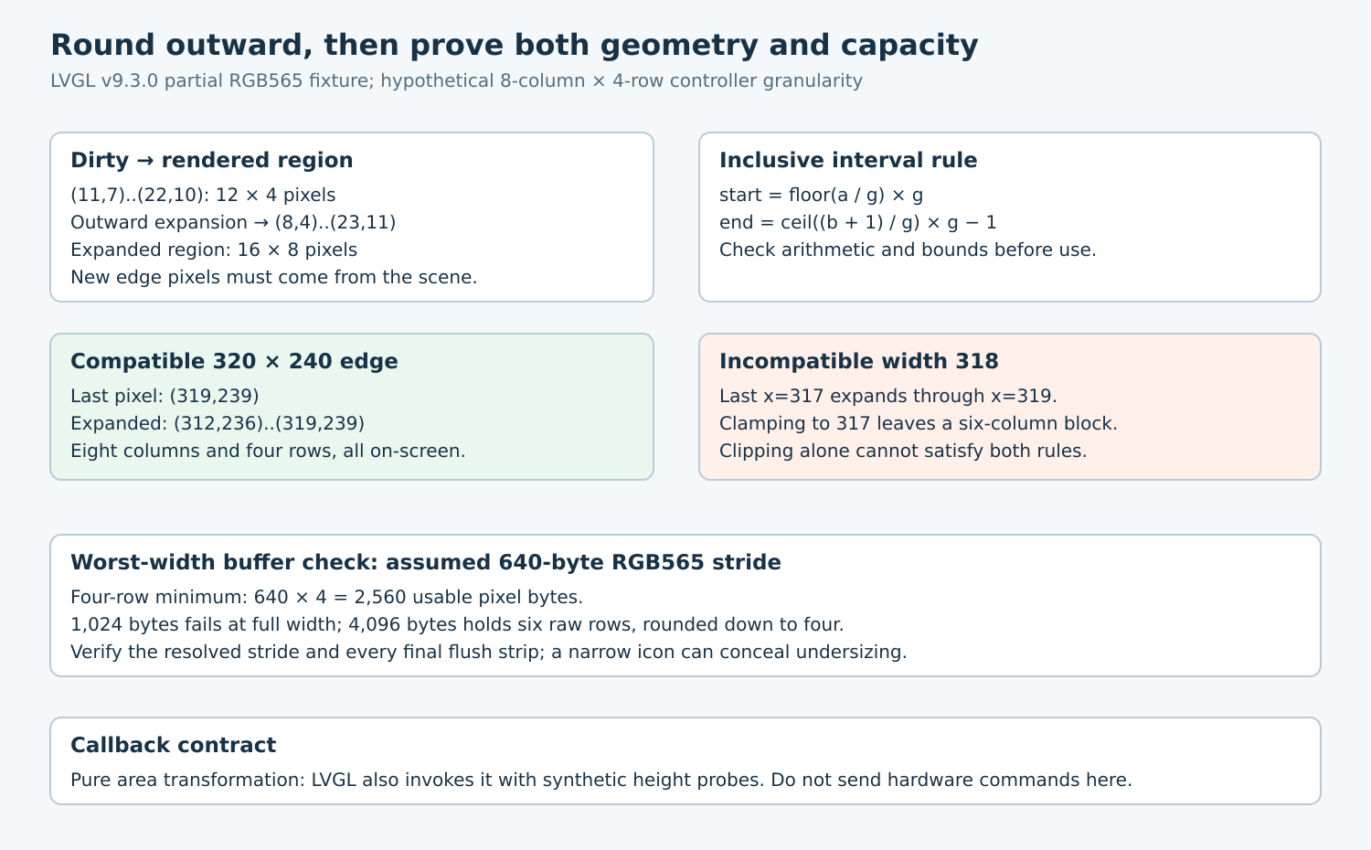
The area API uses inclusive endpoints: x1=x2 is one pixel wide. For a nonnegative interval [a,b] and positive block size g, expand the beginning to floor(a/g)×g and the end to ceil((b+1)/g)×g−1. Use checked wide arithmetic for b+1 and the subsequent multiplication. Reject inverted intervals before applying the formula.
For the hypothetical eight-by-four rule, the dirty rectangle (11,7)..(22,10) becomes (8,4)..(23,11). Its original 12×4 pixels become 16×8 pixels. The additional pixels must be rendered from the scene, not filled with an arbitrary padding color that overwrites neighboring content.
2. Put rounding on the invalidation event
The redraw-constraint guide registers a display callback for LV_EVENT_INVALIDATE_AREA and obtains the mutable area through lv_event_get_invalidated_area. Adapt that pattern to the verified granularity. Keep the callback deterministic and side-effect free apart from the area edit.
Do not move this expansion into the flush callback. The renderer would have produced pixels for the smaller region, while the transport would request a larger one. That can consume unrelated memory or send stale edge pixels. The flush path should verify the already-rendered window and its storage contract.
In the tagged invalidation path, clipping to the screen occurs before the custom invalidation event. There is no second screen intersection immediately after that callback. Consequently, a callback that rounds beyond the right or bottom boundary cannot rely on an automatic post-callback repair.
Full render mode returns through its whole-screen path before this custom event. Invalidation-list overflow can also substitute the whole screen. Validate the entire logical screen against the transport rule, even when the normal workload changes only a small icon.
3. Resolve incompatible edges explicitly
A 320×240 logical display is compatible with the hypothetical block sizes. Its last pixel (319,239) expands to x=312..319 and y=236..239. All coordinates remain on-screen, with eight columns and four rows.
A 318-pixel-wide display is different. Expanding its last pixel at x=317 reaches x=319. Clipping the result back to x=317 leaves six columns in the final block, violating the assumed eight-column rule. Both containment and alignment must hold; one cannot silently override the other.
Resolve that mismatch through a documented controller edge exception, an explicitly supported padded physical address space with valid pixel generation, or a different transport strategy. If none exists, reject the configuration. Do not advertise a generic clamp as a complete solution.
Record coordinate transformations separately when adding rotation or offsets. A rule anchored at physical controller column zero may not be equivalent to the same modulo test in the logical display’s coordinates. The baseline intentionally excludes that extra mapping.
4. Size the buffer for the expanded width
In partial mode, LVGL can divide an invalidated region into horizontal strips. The exact get_max_row implementation calculates available rows using the resolved stride and buffer capacity, then sends trial areas through the invalidation callback while seeking a fitting rounded height. Those probes are geometry calculations, not fresh application damage notifications.
Therefore the callback must tolerate a synthetic area beginning at (0,0), including a one-column trial width. Do not issue controller commands, increment a dirty-frame counter or attach application meaning to every invocation. A logging fixture should distinguish these probes from final flush rectangles.
For an explicitly assumed tightly packed RGB565 stride of 640 bytes at width 320, four rows require 2,560 usable pixel bytes. A 1,024-byte buffer cannot hold that minimum block at full width, even though a narrow test icon might fit. A 4,096-byte capacity admits six raw rows, but only four after rounding down to complete four-row units.
Read the resolved stride from the selected draw-buffer configuration; alignment handlers can change it. The arithmetic above is not a universal LVGL allocation size. Indexed palettes and other formats add different storage conditions. The display setup guide also distinguishes partial buffers from full-screen storage modes.
5. Exercise boundaries and observe actual flushes
| Input on 320×240 | Expected expanded area |
|---|---|
| (0,0)..(0,0) | (0,0)..(7,3) |
| (8,4)..(15,7) | Unchanged |
| (11,7)..(22,10) | (8,4)..(23,11) |
| (319,239)..(319,239) | (312,236)..(319,239) |
Check containment of the original clipped area, nonnegative coordinates, final screen bounds, aligned starts and aligned exclusive ends. Apply rounding twice and require the same result. Sweep points immediately before and after each block boundary, then add overlapping invalidations and a forced whole-screen update.
At flush, record the final rectangle, stride, usable buffer size and required byte range. Use guard storage and a diagnostic pattern around the original dirty region to detect overrun and incorrect regenerated edges. Compare every emitted strip with the hardware’s window rule, including the final strip. A correct aggregate dirty rectangle alone does not prove all transfers are valid.
Accept the port when geometry, actual flush windows and allocation bounds agree for narrow changes and worst-width updates. Preserve the incompatible-edge rejection as a regression case so a later resolution change cannot quietly turn a correct rounder into an out-of-bounds transfer.