MCUboot Swap Modes and Flash Wear: Check the Scratch-Area Cost Before Choosing a Layout
Choose an MCUboot swap mode from flash geometry, usable image capacity, per-region erase cost, and interrupted-update recovery. A small scratch partition can save address space while concentrating erase cycles. Removing scratch does not remove flash wear; offset and move modes distribute work differently and impose their own layout requirements.
This comparison is pinned to the MCUboot v2.2.0 design and image-tool documentation. It is an explanatory baseline, not a recommendation to deploy that revision without reviewing later fixes and the vendor branch. The numeric example is hypothetical. No flash endurance, swap timing, or power-loss behavior was measured on hardware for this article.
1. Start with the real flash geometry
Prepare a sector-by-sector map from the exact device documentation and the deployed flash driver’s reported layout. Record erase sizes, programming alignment, primary and secondary boundaries, reserved bootloader space, and trailer placement. Include external flash separately. A partition’s total byte count does not prove that its sector sequence matches the selected algorithm.
Compare that map with the generated bootloader and application configuration. Resolve disagreements before calculating wear. A board-description file that claims uniform sectors cannot make nonuniform hardware uniform. Also identify where the image receiver starts writing and which component owns erasing the secondary slot.
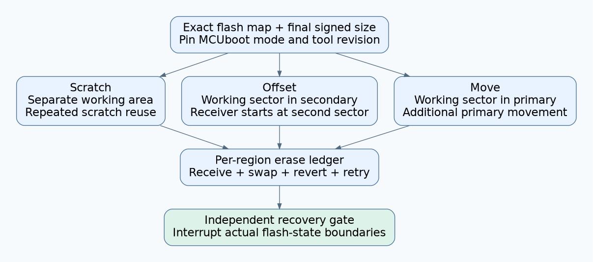
The MCUboot v2.2.0 design requires scratch to hold at least the largest sector involved in the swap. Its offset and move descriptions assume matching slot sector layouts with equal-sized sectors. Offset reserves an extra sector in the secondary side; move reserves one in the primary side. These are algorithm constraints, not interchangeable partition labels.
2. Account for image overhead before comparing modes
Estimate capacity using the final signed artifact and bootloader layout, not only the application binary. The v2.2.0 image-tool documentation describes image preparation with the header, signing metadata, and trailer assumptions expected by the bootloader. Match the tool revision and configuration to the bootloader instead of mixing a new image tool with an unexamined older layout.
For each candidate mode, produce a build artifact near the intended maximum size and verify the accepted limit through the maintained tooling. Include a deliberately oversized artifact and require a clear rejection. Keep the limit calculation, generated partition map, and artifact hash together. This prevents an optimistic spreadsheet from becoming the only evidence that a future release will fit.
Pay particular attention to secondary-slot placement for offset mode: the update image starts at its second sector in the documented design. The receiver must understand that placement. Changing only a bootloader configuration option while leaving the download writer unchanged is not a qualified migration.
3. Compare erase work by region
| Mode | Distinct layout cost | Wear question to answer |
|---|---|---|
| Scratch | Separate scratch area; it must accommodate the participating sector geometry | How often is each scratch sector reused during one swap? |
| Offset | Working sector in the secondary slot; image receiver uses the required offset | What is the combined secondary erase cost of receiving and swapping? |
| Move | Working sector in the primary slot; primary data is moved before replacement | How do extra primary erase passes compare with secondary receiving plus swap work? |
The pinned design models one erase cycle per slot during an offset swap, and two primary versus one secondary cycle during a move swap. For scratch, the approximate reuse multiplier is image size divided by scratch size. Treat these as algorithm-level accounting inputs. Add image-reception erases, reverts, retries, factory programming, and any application use of the same physical sectors.
Do not compare a “swap-only” number for one mode with a “download plus swap” number for another. Define a transaction boundary, then count every relevant operation within it. Preserve separate totals for primary, secondary, scratch, and metadata regions.
4. Work through a hypothetical scratch budget
Assume uniform 4 KiB sectors, a 192 KiB used image span, and a deliberately hypothetical planning allowance of 6,000 erase cycles per sector. This allowance is not a specification for any real flash device. Ignore other erase consumers temporarily to make the arithmetic visible.
- With 8 KiB scratch, the reuse estimate is 192 / 8 = 24 erase cycles per scratch sector per forward swap. The arithmetic allowance is 6,000 / 24 = 250 forward swaps.
- With 24 KiB scratch, the reuse estimate is 192 / 24 = 8. The corresponding allowance is 6,000 / 8 = 750 forward swaps.
- If every tested update swaps forward and then reverts with the same image span, count approximately twice that swap work. The first scenario would allow only 125 such forward-and-revert pairs before other allowances are deducted.
These values were checked arithmetically, not measured. They are not guaranteed update counts, service-life predictions, or recommendations to operate at a datasheet limit. Substitute the real endurance conditions and apply the product’s required margin. Account for varying image sizes and the largest supported update, rather than assuming every future artifact matches today’s span.
5. Reconcile the model with observed flash operations
Instrument the flash abstraction in a development build to record region, sector, operation type, and update phase. Avoid logging secret image contents. Run one accepted update, one rejected candidate, and one tested revert. Compare observed erase counts with the worksheet and explain every difference.
Check whether the downloader pre-erases an entire slot, whether unsuccessful receives start again, and whether an interrupted operation repeats work. Group counts by physical erase block rather than application buffer writes. Wear is a physical-region concern; a long list of writes is not automatically the same number of erase cycles.
If the logging changes watchdog or timing behavior, use a less intrusive counter method and document the limitation. The qualification objective is a trustworthy accounting boundary, not a verbose trace that creates new failures.
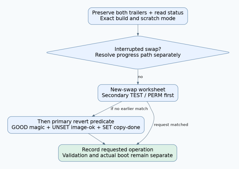
6. Keep power-loss testing independent of wear arithmetic
A layout can have an attractive endurance estimate and still fail recovery. The MCUboot release notes for 2.2.0 include geometry checks and swap-related fixes, illustrating why the exact implementation revision matters. Review relevant subsequent fixes before selecting a production baseline.
On recoverable development hardware, interrupt operations at observed erase, copy, status-update, and confirmation boundaries. Verify which image starts, whether the swap resumes or reverts as intended, and whether the reported image identity matches the bytes actually executed. Test the largest approved artifact and the sector boundary cases of the selected layout.
Include a reset after the candidate starts but before it is confirmed. A successful first boot does not complete the recovery test. Also verify that a watchdog reset during slow flash work reaches a documented recoverable state rather than a repeated reset loop.
7. Make the layout decision reviewable
Accept a mode only with a pinned bootloader/tool configuration, exact flash map, verified image-size limit, per-region erase ledger, and interruption results. If scratch meets capacity but misses the lifetime budget, evaluate a larger scratch area or another supported mode. If an alternative requires changing installed partition boundaries, treat that migration as a separate risk.
The final decision should explain which region limits the budget and which assumptions remain untested. Avoid describing a mode as universally “more reliable” or “wear-free.” The useful comparison is the behavior of the selected algorithm on the actual flash geometry under the product’s complete update lifecycle.