Power-Supply Changeover: Keep Firmware State Consistent When USB or Battery Is Removed
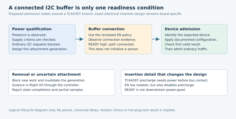
Represent external-input validity, battery capability, charging state, and system-rail continuity as separate facts. When USB or a battery is removed, recompute the operating state from fresh observations. A charger status pin is not a complete description of which source is sustaining the load or whether the processor remained within its supply limits.
Applicability: the concrete status and power-path example is Texas Instruments BQ24074, using SLUS810N, revised October 2021. The product state machine and removal tests are hypothetical. No battery profile, source current, hold-up duration, charging configuration, or measured switchover result is prescribed.
1. Define facts before naming product states
Build an observation record containing external-input validity, battery evidence, charge indication, system-rail observation, load mode, sample time, and acquisition result. Preserve unknown separately from false. A failed battery measurement should not silently become “battery absent” or “battery full.”
Then define product states from those observations: externally supplied with qualified backup, externally supplied without qualified backup, battery-supplied, uncertain supply, and reset/recovery. Treat these as application states whose entry conditions must be specified, not as built-in modes reported by the charger.
Include the physical wiring of status pull-ups and the processor’s input domain. If a pull-up disappears with the removed source, a sampled low or floating node may no longer have its normal meaning. Validate that signal path across the permitted supply combinations.
2. Decode PGOOD and CHG with their actual ambiguity
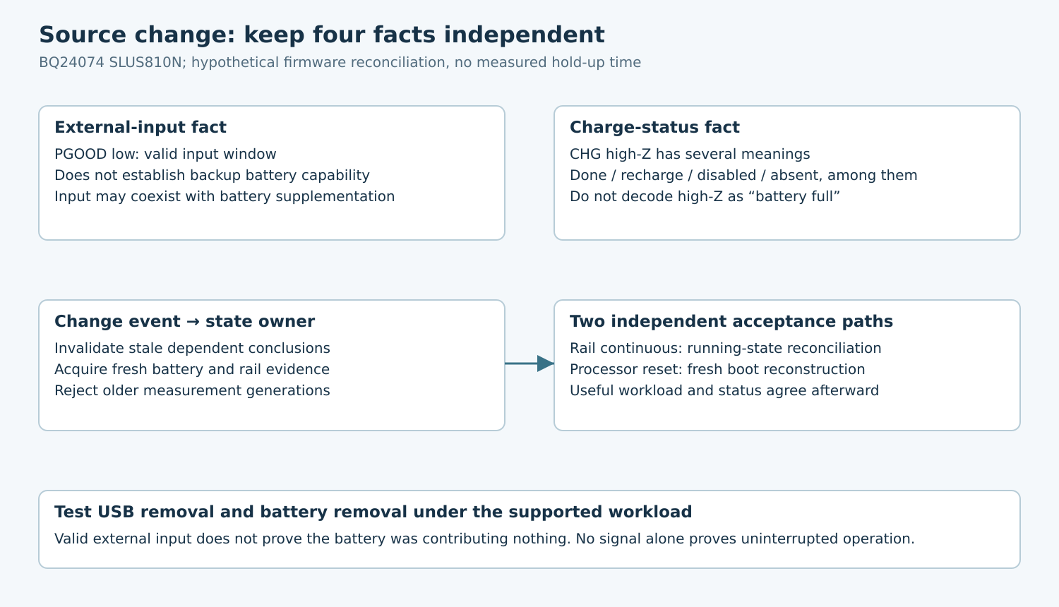
The BQ24074 data sheet, section 9.3.5.7, defines PGOOD as an open-drain indication of valid input power. It is low inside the documented input-valid window and high impedance outside it. It does not report battery state of charge or a guaranteed system-load margin.
CHG also has multiple meanings. Its high-impedance states include charge completion, recharge after termination, disabled/no-valid-input conditions, and battery absence. Low during the first charge cycle can include charging suspended by the thermal loop. Thus one binary sample cannot uniquely identify “full,” “missing,” or “currently receiving charge.”
Create a decoding table with an allowed conclusion and a forbidden conclusion for each observation. For example, CHG high impedance permits “charge-status output released”; it does not independently permit “battery ready to sustain the system.” Use additional qualified telemetry or a documented detection mechanism for the stronger claim.
Record pin polarity explicitly in firmware interfaces. A boolean named charger_good should not sometimes mean the physical pin level and sometimes mean decoded validity. Keep raw input and interpreted state available together during qualification.
3. Include battery supplementation while input is present
Sections 9.3.4.1.2 and 9.3.4.1.3 describe DPPM reducing charge current as load demand rises, followed by battery supplementation under the specified conditions. External input being valid therefore does not establish that the battery is idle.
Consider a hypothetical product that increases processing or radio activity while USB is attached. Its battery may be contributing during that workload. Removing the battery can then change the available load support even though PGOOD continues indicating valid input.
This is why the removal matrix needs a high-demand operating case as well as an idle case. Qualify the actual source, cable, current-limit configuration, battery, downstream regulator, and load together. Do not infer adequate input capability from connector presence or a charger indicator alone.
Also distinguish disabling charging from disconnecting the system supply. The BQ24074 CE description states that disabling battery charging leaves OUT active and supplementation available. Do not implement a product power-off action by assuming CE removes every source from the load.
4. Reconcile events through one state owner
Let interrupt or polling paths record observations and notify one power-state owner. That owner should produce a coherent state generation, rather than allowing unrelated handlers to overwrite flags such as on_usb, charging, and battery_ready independently.
When a source changes, invalidate dependent conclusions and reacquire the evidence needed for the new state. Preserve a generation or event sequence so a slow measurement started before removal cannot overwrite newer observations after removal. Store the acquisition time, not merely the time a UI displayed the result.
Define how contact bounce and brief source changes affect policy. A UI may wait for a stable indication, while a rail supervisor must respond according to its hardware protection contract. Do not impose one arbitrary debounce interval on every consumer or delay a protective action solely to make the display look stable.
On restart, derive state from the current hardware and available reset evidence. A retained “USB connected” flag is historical information, not proof that USB remains connected. Publish uncertainty until the relevant observations are established.
5. Test removal in both directions
| Proposed transition | Required interpretation |
|---|---|
| Remove USB with qualified battery attached | Confirm rail continuity or defined reset, then battery-supplied state. |
| Remove battery while valid USB remains | Reassess backup capability; verify the current workload remains supportable. |
| Remove the only qualified source | Expect the product’s defined power-loss behavior, not indefinite software recovery. |
| Reconnect a source during recovery | Rebuild state from fresh evidence without applying stale completion events. |
| Repeat at an allowed high-demand load | Check supplementation and source-limit assumptions independently of idle behavior. |
Use a protected, recoverable development fixture and a reviewed source-disconnect mechanism. Follow battery handling and charger requirements; do not short a pack or bypass its protection to create a test condition. A suitable battery simulator can be preferable where the design and lab procedure support it.
6. Capture continuity separately from firmware consistency
Observe input, battery and system rail at the appropriate points, plus status pins and a processor reset or boot marker. Choose measurement limits from the actual processor and regulator documentation. Keep analog evidence alongside event timestamps and state generations.
If the processor resets, test correct restart rather than pretending the running-state machine survived. If it stays alive, check that workload policy, telemetry, and user-visible status converge to the new physical configuration. Those are different acceptance paths.
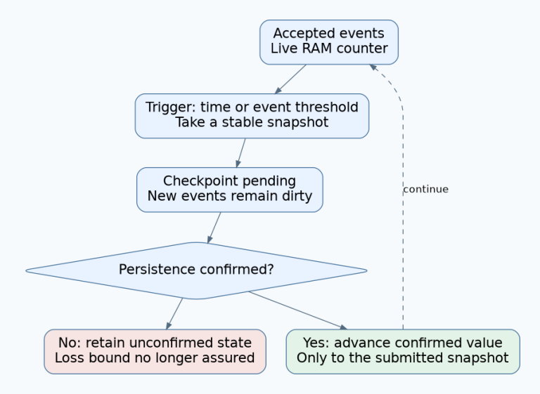
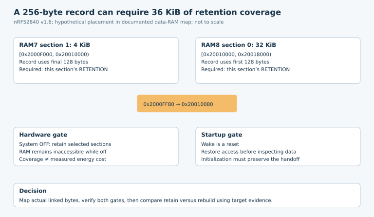
A last-moment software handler has no guaranteed execution budget merely because a source-loss interrupt exists. Any required persistence or orderly shutdown needs a separately qualified reserve and storage procedure. This article does not establish such a reserve.
7. Release a transition matrix with explicit unknowns
The final artifact should include signal semantics, allowed state conclusions, source-change ordering, stale-observation rejection, and rail/reset results for each supported transition. Retain the exact charger part and board configuration with the evidence.
Accept the design when firmware state remains consistent with what the hardware can actually establish, including uncertainty and restart. The goal is reliable source-change behavior, not a universal promise that every removal preserves uninterrupted operation.