PWM Requested State Versus Actual Waveform: Verify Quantization and Disabled Output
A PWM request describes the desired waveform, not a measurement of the waveform the hardware produced. Check the driver’s quantization and state-reporting contract, then capture period, active time, polarity, and disabled behavior at the relevant output. A successful apply call or matching cached state cannot establish exact timing or a safe inactive level.
Applicability: the API and implementation references are Linux v6.12, with pwm-imx27 as a concrete driver example. The numerical clock and requests below are hypothetical arithmetic inputs to that implementation, not a claimed board clock or tested hardware configuration. Board voltage, loading, reset state, and supported clock constraints need their own device documentation.
1. Define the waveform requirement at the load
Record requested period, active duration, polarity, enabled state, and the permitted error for each. State whether the load cares about individual edges, average power, pulse count, or a sustained inactive level. These requirements are different even if the user interface exposes only a percentage slider.
Identify the observation point. A correct controller output can be inverted or gated before reaching the load. Include pinmux, level translation, external enable signals, and power domains in the measurement plan. Keep that electrical path separate from the PWM core’s logical polarity.
Set boundary cases deliberately: zero active time, a small nonzero request, middle duty, near-full duty, full duty, and disabled. Avoid applying these patterns to a consequential load without a controlled development fixture.
2. Separate requested, cached, and implemented state
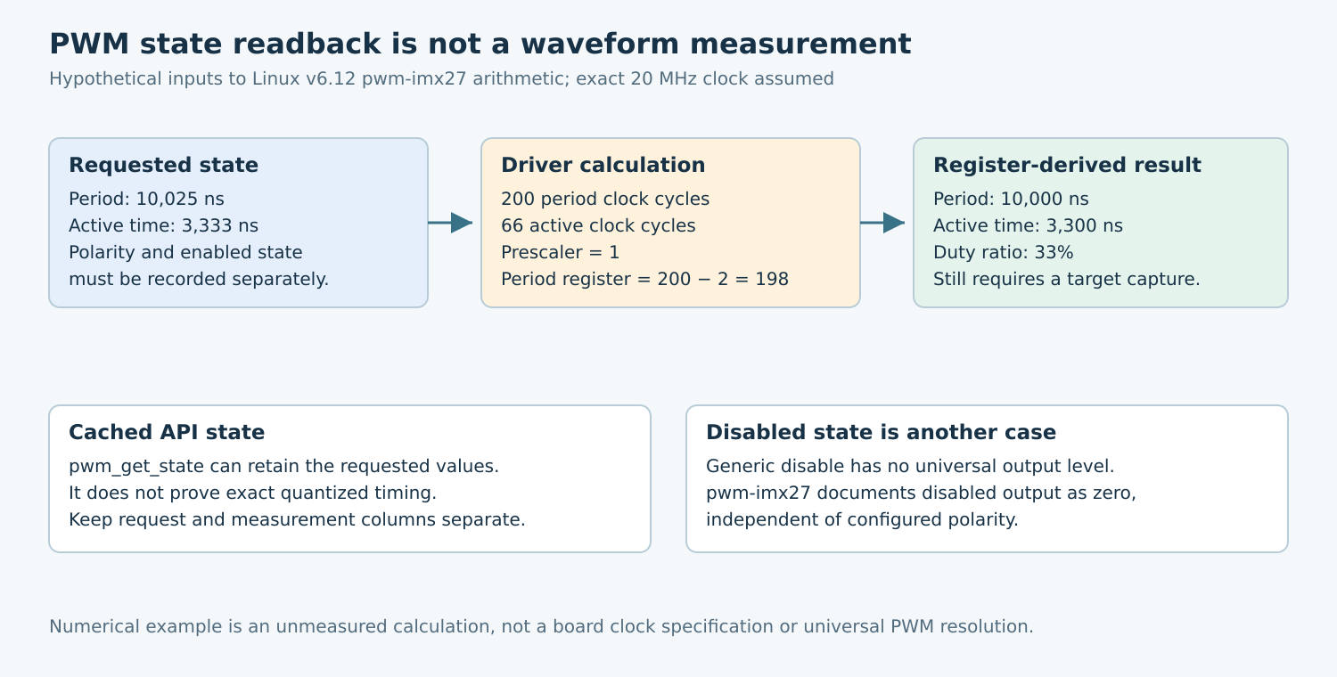
The v6.12 PWM interface documentation states that pwm_get_state reports the state passed to the last apply operation, which can differ from what hardware implements. It is not a general readback of the quantized waveform.
Use separate worksheet columns for the application request, accepted framework state, driver-derived register values, and measured output. If one column is unavailable, mark it unknown. Do not copy the requested period into the measured column because the API returned success.
The framework also distinguishes ordinary waveform use from usage_power, which can give a supporting driver more freedom over signal shape while preserving the relevant power output. Do not enable such freedom for a consumer that requires a particular edge or phase relationship without reviewing the consequence.
3. Calculate quantization from the selected driver
The v6.12 pwm-imx27 implementation converts requested nanoseconds to integer clock cycles, selects a prescaler, and programs a period register whose effective period uses the register value plus two. Its calculation and range details belong to this implementation, not every PWM controller.
For a hypothetical peripheral clock of exactly 20 MHz, one unprescaled cycle is 50 ns. Give the driver a period request of 10,025 ns and active-time request of 3,333 ns. Its integer calculation yields 200 period cycles and 66 active cycles with prescaler one; the period register value is 198.
The corresponding ideal register-derived values are 10,000 ns period and 3,300 ns active time. Their duty ratio is 33 percent. This fixture is chosen away from the minimum-period and prescaler-change boundaries. It demonstrates rounding loss; it is not evidence that a particular board produces those times.
Repeat the calculation on both sides of a prescaler boundary using the actual driver and a legal clock configuration. A one-step request change can alter the timing resolution. Check period and active-time errors separately instead of assuming that preserving their approximate ratio satisfies both requirements.
4. Treat disabled output as a separate contract
The generic PWM API warns consumers not to rely on a disabled PWM’s output state. Where the required state is the polarity-defined inactive level, it recommends an enabled PWM with zero duty rather than assuming disable produces that level. Validate this choice for the actual load and controller.
The pwm-imx27 source documents a specific limitation: its disabled output is driven to zero independently of configured polarity. Thus an inverted waveform’s inactive level and its disabled level need not be the same. This is driver-specific evidence, not an electrical guarantee for every NXP part or board.
Zero duty also does not mean “no physical voltage” in all polarity configurations. Define active and inactive at the output and then translate through the board path. If the load requires a separate hardware inhibit, preserve that independent mechanism instead of using an assumed PWM-disable level as its replacement.
5. Observe transitions as well as steady state
Use the combined apply interface when changing several PWM parameters together. Separate configuration and enable calls create additional intermediate states to review. Even a combined API operation does not by itself prove an edge-perfect hardware transition; inspect the driver’s update and buffering behavior.
Capture startup, duty changes, period changes, polarity changes where supported, disable, and re-enable. Look for an unexpected short pulse, extended cycle, or interval at the wrong level. Compare the first affected cycle with the later steady waveform.
For the concrete driver, review its sample FIFO and reset paths before interpreting when a new request becomes visible. A software completion time is not automatically the exact boundary of a hardware cycle. Save both the apply-call trace and the output capture when investigating transition anomalies.
6. Build an acceptance matrix with independent evidence
- Resolution: compare nearby requests that should map to the same or adjacent count values.
- Duty boundaries: test zero, the smallest required nonzero pulse, and values near full active time.
- Polarity and disable: measure enabled inactive output and disabled output separately.
- Clock changes: repeat after any supported parent-clock or power-state transition that can affect the counter.
- Resume: verify that the consumer restores the intended state and that the first output interval is acceptable.
Record measurement bandwidth, threshold, timebase accuracy, and load conditions. An instrument’s cursor resolution is not the same as its timing uncertainty. Compare observations with the system tolerance, including source-clock uncertainty, rather than reporting more decimal places than the setup supports.
If the requested state is correct but the waveform fails, classify whether the cause is count quantization, clock selection, update timing, pin routing, or electrical loading. Changing the requested duty can hide one symptom while leaving the underlying contract unexplained.
No PWM apply operation or waveform measurement was performed for this article. The deliverable is a request-to-register calculation and a boundary-state capture matrix. Acceptance requires the actual output to satisfy the load’s timing and inactive-state requirements, not merely an API object that repeats the desired settings.