STM32G474 USB-C Cold Start: Preserve Dead-Battery Detection Until UCPD Takes Over
A USB-C sink has to advertise its presence before the firmware that normally manages the port can run. On an unpowered STM32G474, that first advertisement depends on the dead-battery termination path. Once power arrives, firmware must transfer control without accidentally removing the sink termination.
This article examines a proposed STM32G474RE LQFP64 sink board using the integrated UCPD dead-battery feature. The reference is RM0440 Rev 9, sections 46.4.6 and 46.5, together with DS12288 Rev 6, section 4 and its pin-table footnote 6. It is a cold-start and takeover review, not a complete USB-PD power design.
Trace both CC paths while the MCU has no power
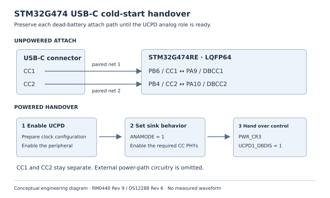
RM0440 specifies that the unpowered device presents dead-battery Rd only when each DBCC signal is connected to its corresponding CC signal. The G474 mapping is:
- Connector CC1 reaches PB6,
UCPD1_CC1; PA9,UCPD1_DBCC1, connects to that same CC1 path. - Connector CC2 reaches PB4,
UCPD1_CC2; PA10,UCPD1_DBCC2, connects to that same CC2 path.
These are paired connections, not permission to join CC1 and CC2 together. Review the selected package pin table and the board netlist, including protection components and any switches that interrupt the connection. A connector labelled USB-C does not establish that either DBCC route exists.
The manual gives a different connection for products that do not require dead-battery behavior: both DBCC pins go to ground. Copying that source-only arrangement into a bus-powered sink defeats the intended startup path. Also account for the other functions on PA9, PA10 and PB4; they cannot be treated as unrelated spare pins after the board assigns them this role.
Transfer termination ownership in the documented order
After reset, PWR_CR3.UCPD1_DBDIS is clear and dead-battery behavior is enabled. Setting that bit removes the dead-battery pull-down behavior. The PWR register description explicitly requires UCPD initialization before this handover.
Review the startup path as an ordered operation:
- Prepare the UCPD clock-divider configuration and enable the peripheral as described in section 46.5.1.
- Program the intended analog role through
ANAMODEandANASUBMODE, with the required CC PHYs enabled throughCCENABLE. - Only then set
PWR_CR3.UCPD1_DBDISto hand control to UCPD. - Continue the Type-C state machine using the CC indications and VBUS-presence information.
For the sink role, ANAMODE = 1; Table 440 treats ANASUBMODE as don’t-care in this role. Enabling both CC PHYs is the documented normal sink/source use. These facts do not replace the remainder of peripheral initialization or the port state machine.
A generic early-startup routine that disables dead-battery behavior before the UCPD owner runs is therefore a concrete review target. Search every write to UCPD1_DBDIS, including board support and low-power code. A later correct initialization cannot retroactively preserve a termination that earlier code removed.
Distinguish failure before boot from failure at takeover
Use a reviewed, protected development fixture and observe CC1, CC2, VBUS and the MCU supply, together with a firmware boot marker. Do not inject arbitrary voltages into CC pins to imitate an attachment.
If VBUS never becomes available from a compliant source, start with the unpowered termination route and connector orientation. If power arrives and then disappears around a repeatable initialization point, compare that point with the ownership transition. A boot log ending there is a clue, not proof: supply loading, reset circuitry and the external power path can produce similar symptoms.
Run the proposed check with the cable in both orientations. One working orientation can conceal a missing or incorrect second DBCC-to-CC path. Repeat from a genuinely unpowered condition; a debugger or auxiliary supply can make firmware run early enough to hide the defect. Remove such assistance only through the board’s safe, documented power arrangement.
Keep the acceptance boundary narrow
The acceptance record should identify the exact package, the two paired nets, the UCPD initialization order and the observed rail/CC behavior at takeover. Record both unpowered startup and powered reset as separate cases because their initial electrical states differ.
UCPD does not directly implement the external VBUS-generation circuitry or VCONN load switch. A stable CC transition alone does not qualify the power path, negotiated operating point, current limits or USB-PD compliance. It also says nothing about a USB data interface.
No board measurements were performed here. The engineering decision is specific: preserve the hardware attach advertisement until a correctly configured UCPD peripheral can own it, then verify that transition on the actual sink board.