STM32H563 GPDMA Dynamic Lists: Decode Each Node from the Previous Update Mask
A valid STM32H563 GPDMA node address does not prove that the words at that address describe the intended registers. In a dynamic linked list, the current link register’s update bits define the layout of the next node. A compact node has no self-contained header that lets the DMA discover which fields the author intended to place there.
Decode each incoming link before decoding its destination node. This article uses RM0481 Rev 5, sections 16.4.5–16.4.6, with a linear-addressing H563 channel and schematic register values. It does not supply executable binary descriptors or claim a completed DMA transfer.
Treat the previous mask as the next node’s grammar
For a linear channel, the possible memory fields follow the order CxTR1, CxTR2, CxBR1, CxSAR, CxDAR, CxLLR. Each field is present only when its corresponding update bit in the current CxLLR is set. Unselected fields consume no word in the compact memory structure.
Consequently, clearing UT1 does more than retain the transfer-control setting. It removes the first word from the next node’s layout. If software leaves a placeholder there, the DMA interprets that placeholder as the first selected register value, shifting every later interpretation.
A static list that updates every supported field can conceal this mistake because every node has the familiar full layout. Optimizing the same list into compact nodes requires regenerating both the incoming masks and the packed field sequence. Editing one side alone is an incompatible format change.
Trace three transfers with different incoming masks
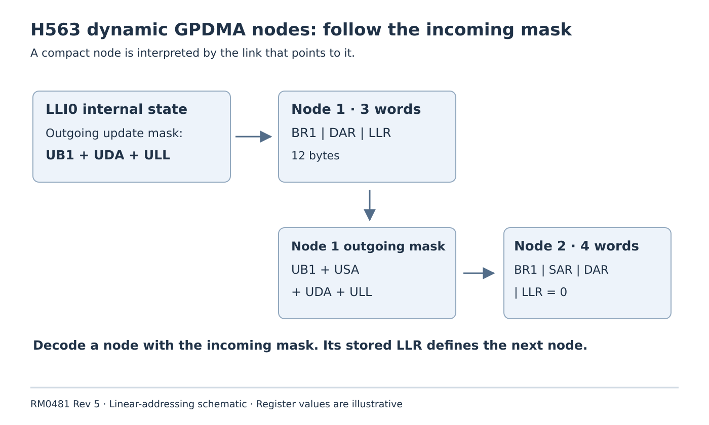
Suppose the initial internal register file, LLI0, performs a bounded transfer from a fixed source to destination A. Its link points to memory node 1 with only UB1, UDA and ULL set. All other update bits are zero.
Node 1 must therefore contain these three contiguous 32-bit words:
word 0: BR1 for transfer 1
word 1: destination B
word 2: LLR describing node 2
That final word describes the next transition. Choose its update mask as UB1, USA, UDA and ULL, with the remaining update bits zero. The resulting node 2 contains four words:
word 0: BR1 for transfer 2
word 1: new fixed source
word 2: destination C
word 3: LLR = 0 for the final link
When node 1 is fetched, its first word updates BR1, its second updates DAR, and its third updates LLR. When node 2 is fetched, the different incoming mask makes its second word update SAR; DAR now comes from the third word. Both layouts are correct despite their different lengths.
An inspector that labels every second word “destination” would report a plausible address for node 2 while misunderstanding the transfer. Conversely, using node 2’s own final zero link to decode node 2 would select no fields at all. The incoming edge supplies the layout; the stored outgoing edge describes the successor.
Account for state changed by the transfer itself
Omitted fields retain the register state present at the link transition. That state may differ from the values initially programmed because data execution updates counters and applicable addresses. This matters especially when a compact-node generator assumes that an unchanged configuration means an unchanged live register.
The example deliberately reloads BR1 for each new transfer. Its fixed-source assumption avoids relying on an incremented source address being the same as the original source. A real incrementing transfer needs a separate calculation of the carried address or an explicit reload through the corresponding update bit.
Review the state in two steps: first apply the completed transfer’s register effects, then apply the successor’s selected updates. A generator that only compares adjacent application configuration objects can omit a reload that the hardware needs after execution.
Validate the link interval after validating its grammar
The next-node address combines CxLBAR with the link offset in CxLLR. RM0481 requires the entire node structure to fit inside that selected 64-Kbyte link-addressable window. Checking only the first word misses a compact node whose final word crosses the boundary.
Compute the node’s length from its incoming update mask, using the selected channel’s supported register set. Then check alignment and the complete interval. For this example, the compact nodes occupy 12 and 16 bytes respectively. These lengths are illustrative arithmetic, not universal descriptor sizes; 2D channels also have their applicable additional fields.
Review a decoded transcript, not just a memory dump
For each link, preserve the incoming mask, node address, selected field names, consumed words and resulting register state. Include a negative fixture with an extra placeholder word and another with a mismatched incoming mask. A software decoder should expose the first changed interpretation before any hardware run.
Use a separate controlled target test for actual transfer results and completion. A zero final LLR belongs to the documented channel-completion conditions together with completed counters; it is not a substitute for checking the whole transfer state.
The release artifact is a node-by-node state transcript. It establishes which word updates which register, why omitted values remain valid after the preceding transfer, and where the list ends.