STM32H750 Supply Startup: Why Reset May Not Undo a Wrong PWR_CR3 Write
An STM32H750 that stops while waiting for ACTVOSRDY may have a board-supply mismatch or an incorrectly committed startup configuration. Repeating writes after a reset-button press is not necessarily a fresh attempt: the relevant PWR_CR3 configuration is tied to power-on reset, not every reset source.
The detailed contract is in RM0433 Rev 9, Table 34 and sections 6.4.1 and 6.8.4. Read it alongside the H750-specific supply and VCAP information in DS12556 Rev 8. This is a startup diagnosis, not a proposal to experiment with arbitrary power-register values.
Match firmware to the physical core supply
RM0433 distinguishes LDO supply from bypass using an external core supply. Table 34 gives LDOEN equal to one and BYPASS equal to zero for LDO operation, and the opposite combination for bypass. The remaining combinations are illegal.
The board must actually implement the selected supply arrangement. A software setting cannot provide an external core supply that the schematic omitted, and a generic H7 example may target a different device's power hardware.
AN4938 Rev 7 includes H750 in its applicability list, but it also discusses features available only on some covered devices. Use the H750 datasheet to resolve the exact circuit rather than copying every power option in a family-wide note.
Check VCAP components as part of that circuit. The H750 datasheet gives different decoupling requirements for regulator operation and bypass. Those are not interchangeable stuffing options to be chosen after firmware is written.
Find the first write after power-on reset
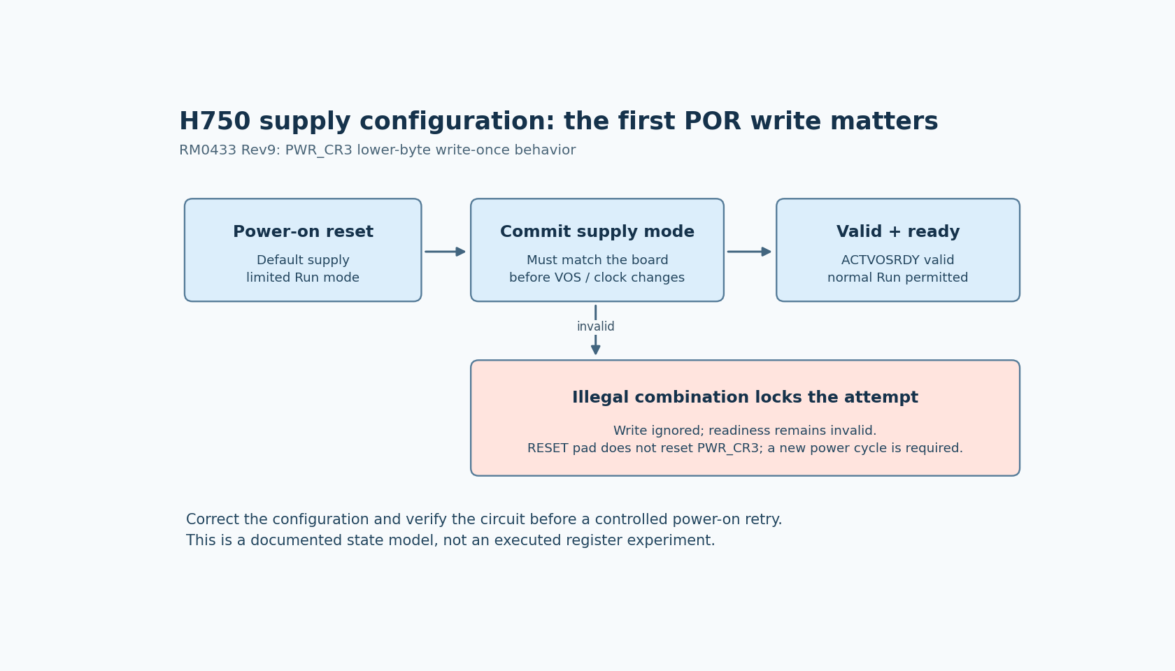
The reference manual says the lower byte of PWR_CR3 is written once after POR and must be written before changing the voltage-scaling level or system clock frequency. It also says the register is not reset by the RESET pad or a wakeup from Standby.
That makes the first writer important. Inspect boot code, generated initialization, board support and application startup for the code that commits the supply configuration. A later function can look correct in isolation while arriving after the write-once opportunity was consumed.
Record the reset path used during debugging. A debugger restart or reset-button operation should not be described as equivalent to a new power-on sequence without checking the documented reset behavior.
The useful review artifact is a single owner and order for supply initialization. Avoid two layers each assuming it can independently choose the board's supply mode.
An illegal combination is not a harmless rejected write
RM0433 describes a specific failure case: an invalid LDOEN/BYPASS combination is ignored, but the write-once mechanism locks. The default supply configuration remains, further writes are ignored and ACTVOSRDY continues to indicate invalid levels. The manual requires a power cycle before a new value can be written.
This explains why repeatedly trying the corrected setting through an ordinary reset may fail to change the outcome. It also explains why a timeout workaround is not an adequate repair: skipping the readiness condition does not establish a valid supply configuration.
On recoverable development hardware, use the documented power-on sequence after correcting the initialization path and verifying the board. Do not deliberately write illegal combinations as an exploratory test, and do not power-cycle equipment whose operating state or connected loads make that unsafe.
Respect the transition out of limited Run mode
The startup description says the CPU initially enters limited Run mode. After the supply configuration is programmed, ACTVOSRDY must indicate valid voltage levels before normal operation. While levels are invalid, the manual prohibits RAM writes and changing VOS.
Review the early startup sequence against that restriction, including code inserted by a framework or instrumentation. A wait loop is a symptom location, not proof that the loop itself is defective.
Once the supply is valid, later clock and voltage choices still need the actual silicon's operating limits. DS12556 separates revision Y and revision V electrical characteristics and explicitly associates the 480 MHz maximum with revision V. A product-page frequency headline is not sufficient evidence for every H750 unit.
Close the diagnosis with a board-specific startup record
Capture the complete part and silicon revision, board supply mode, VCAP implementation, reset source, first configuration writer and readiness observation. If the hardware arrangement and committed bits disagree, resolve that mismatch before investigating application tasks.
No register writes, board power changes or measurements were performed here. The practical outcome is a deterministic startup contract: the correct supply mode is committed once at the correct reset boundary, readiness is established before dependent operations, and subsequent frequency choices use the appropriate silicon limits.