STM32WB Stop Entry: Preserve the Two-Core Clock Handoff
Choosing a valid STM32WB55 low-power mode is only part of entering it correctly. CPU1 and CPU2 also share a clock-transition protocol. Replacing the example idle path with a custom RTOS hook can break that protocol even when the PWR mode selection itself is correct.
AN5289 Rev 18 assigns distinct responsibilities to hardware semaphores 3 and 4 and specifies where clock restoration occurs relative to interrupt execution. Preserve that sequence before trying to optimize the idle hook's overhead.
The difficult case is opposite movement by the two cores
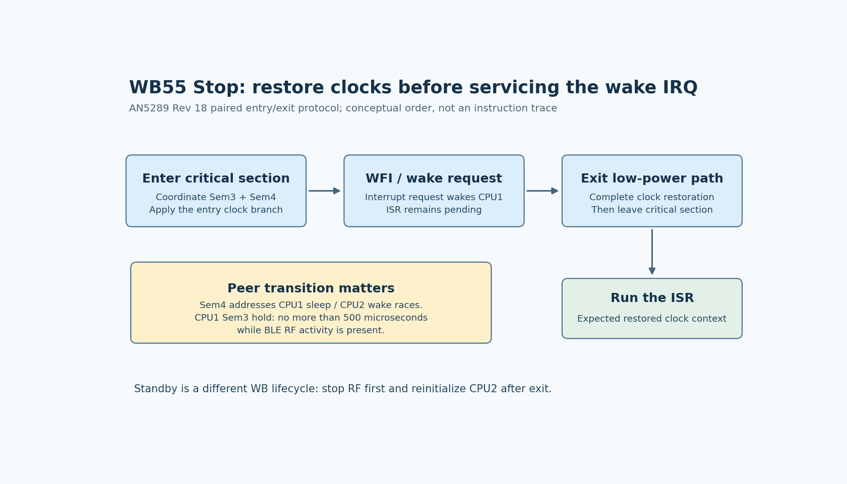
AN5289 section 4.3 describes semaphore 3 as part of low-power clock coordination. It states that CPU1 must not keep it locked for more than 500 microseconds while BLE RF activity is present.
Semaphore 4 handles the race in which one processor exits low power while the other enters it. This is different from two tasks on CPU1 agreeing that the application is idle. The peer can be changing the shared clock situation while CPU1 is evaluating its own next state.
A local idle flag, scheduler lock or atomic Boolean cannot replace this cross-core protocol. Keep the hardware-semaphore ownership and the peer's power-state observations in the implementation review. The RM0434 Rev 16 PWR and RCC descriptions provide the underlying dual-core state and clock registers.
Review the entry and exit algorithms as a pair
AN5289 Figures 6 and 7 describe the CPU1 Stop entry and exit procedures. The entry algorithm obtains semaphore 3 and uses semaphore 4 together with CPU2's state to decide the clock handoff. In its applicable branch, it enables HSI, waits for readiness and the selected system clock, and updates the SMPS clock selection before entering the low-power state.
The exit path releases semaphore 4, reacquires the clock-coordination semaphore and restores clocks according to the use case. The note specifically requires the resulting clock configuration to provide CPU2 with its required 32 MHz operation.
This is not a universal register script to copy into every WB project. The point is that the clock decision spans both sides of WFI. Keeping the entry code while replacing the exit code with a generic “restore system clock” call can lose a required part of the inter-core handoff.
Restore the clock context before running the interrupt handler
Figure 5 shows the entry routine, WFI and exit routine inside a critical section. In the documented pattern, an interrupt request wakes the processor, but the interrupt service routine runs only after the critical section is exited. This allows the exit routine to restore the expected clock context first.
That ordering matters when an ISR immediately accesses a peripheral or depends on a configured clock rate. Moving interrupt unmasking ahead of the exit procedure changes the environment the ISR sees. A successful wake indication does not establish that its first peripheral operation ran under the intended clocks.
When adapting the code to an RTOS, inspect how the port represents the interrupt mask, enters idle and resumes scheduling. Preserve the documented ordering through the actual compiled path. Do not insert a general-purpose sleep call and assume that it performs the WB-specific restore-before-ISR work.
Treat the 500-microsecond limit as a design constraint
The semaphore-3 limit is not a target for how long every sleep entry should take. It limits how long CPU1 may hold that coordination resource during BLE activity. Extra logging, allocation or unrelated device waits inside the protected interval consume that allowance without helping the clock handoff.
For a proposed timing review, identify the acquisition and release points, then enumerate every branch and wait between them. Qualify the interval on the intended clock configuration and workload with observation that does not itself add substantial delay. A short typical interval is insufficient if an error path can retain the semaphore indefinitely.
Keep this bound separate from the flash protocol's semaphore timing rules. They involve different resources and should not be merged into one generic “hardware semaphore timeout.”
Do not substitute Standby for a difficult Stop integration
AN5289 identifies Stop 2 as the deepest supported mode while RF remains active in this WB model. Entering Standby requires first stopping RF activity and fully reinitializing CPU2 afterward. A deeper mode therefore changes the wireless lifecycle rather than simply fixing an idle-current target.
No sleep transition or power measurement was executed here. A complete port should demonstrate the paired clock handoff, the first useful interrupt after wake and the intended radio behavior. The immediate review question is whether the custom idle hook preserves those obligations, not merely whether it reaches WFI.