STM32G431 Comparator Blanking and Automatic PWM Restart Need One Timing Review
A comparator's raw fault condition and the signal seen by a timer break input can differ during a blanking window. On STM32G431, that distinction matters when PWM outputs are allowed to restart automatically. Review blanking and restart together before claiming that a sustained analog fault keeps switching inhibited.
Scope: STM32G431 COMP and TIM1 using ST RM0440 Rev 9, AN4277 Rev 9, and ES0431 Rev 9. This article develops a proposed timing review for an inactive power-stage fixture. It does not establish a certified safety function, an acceptable fault-energy limit, or measured shutdown latency.
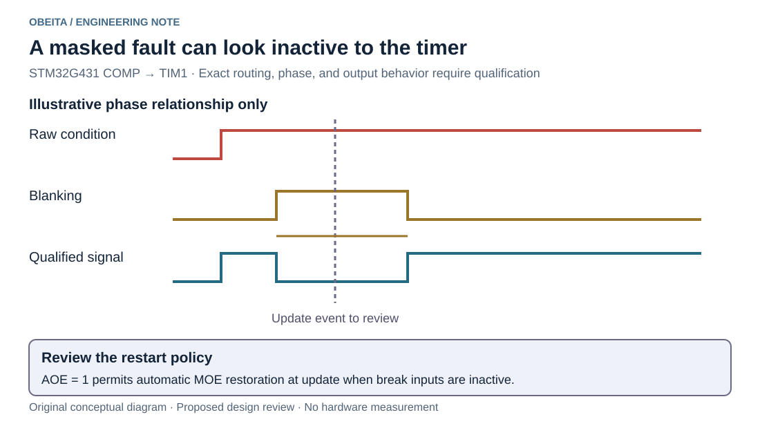
Original conceptual timeline with noninverted comparator output and active-high interpretation. No digital filter is represented. The update event requires qualification; simultaneous-edge ordering is not claimed.
Write down which condition the timer actually sees
RM0440 describes comparator blanking as gating the comparator-stage output with the inverse of a selected timer signal. While blanking is active, the comparator channel's output can be suppressed even if the underlying analog comparison remains asserted. The selected comparator output can then feed a timer break path. ST RM0440 Rev 9 sections 24.3.6 and 29.3.18
The same manual defines AOE as permitting MOE to be restored at an update event when the break inputs are inactive. With AOE clear, software must set MOE. These are different restart policies. Neither clearing a diagnostic flag nor observing a quiet blanked output independently proves that the original fault disappeared.
The practical inference is narrow but important: an application cannot use the blanked comparator level as continuous evidence of analog fault clearance. Whether a specific update produces a restart depends on the selected routing, polarity, timing, and other break sources. Establish that result for the implemented configuration rather than guessing the ordering of coincident edges.
Distinguish the intended noise from the fault you must retain
Blanking can be useful when a known switching transient should not trip a cycle-by-cycle current limiter. That intended rejection window must be justified by the power-stage design. It is not a general instruction to ignore every comparator event near a switching edge.
Create a timing worksheet with five rows: raw comparator condition, blanking source, qualified break condition, update event, and output-enable state. Annotate the PWM period, window placement, and permitted reaction time. Keep the analog threshold and its tolerance in a separate electrical calculation.
Consider a hypothetical 50-microsecond PWM period with a 2-microsecond blanking window. A fault appearing just after the window opens is unobservable through that masked path for nearly the remaining window. This arithmetic is an illustrative blind interval, not a board specification or measured propagation time. Add the actual comparator, filter, output, and driver delays separately.
Do not use filtering as a synonym for blanking
AN4277 distinguishes selectable break filtering from the source-routing choices. Filtering qualifies transitions through a sampling rule; blanking suppresses the comparator output during a chosen interval. Combining them can extend the time before a real condition reaches the output-control decision. ST AN4277 Rev 9
For each configured filter, record its source clock, required samples, and the pulse widths it can reject. Then review a fault beginning near the end of blanking as well as near its beginning. A steady-state filter calculation alone misses the phase-dependent blind interval introduced upstream.
Identify any independent shutdown path required by the system. Do not assume the same masked signal can provide both deliberate transient rejection and uninterrupted evidence of a persistent condition. Selecting an independent path requires a board-level protection design, not simply another interrupt handler.
Choose what authorizes another pulse
For cycle-by-cycle limiting, automatic restart may be intentional. Define which pulses may resume and what bounds the energy delivered during repeated fault cycles. An application that needs a latched shutdown has a different requirement: the restart decision must remain blocked until its specified checks and authorization are satisfied.
Use explicit states such as inhibited, armed, running, and fault-latched in the design record. State which hardware event or software owner can move between them. Keep a telemetry acknowledgment separate from rearming; a user clearing an alarm display should not accidentally authorize another power pulse.
Define the physical output levels for the inhibited state, including the complementary output and gate-driver enable. AN4277 emphasizes the chain from sensing through timer configuration to output behavior and discusses configuration locking. A lock can preserve a chosen configuration, but cannot make an unsuitable restart policy appropriate.
Qualify boundary phases without energizing the load
Begin with the power stage disabled and a suitable bounded stimulus applied through an approved fixture. Observe the selected comparator signal where available, timer status, and actual PWM pins. Use a persistent stimulus extending across several blanking and update periods, not only one short pulse.
Include a fault before arming, just inside the blanking window, just outside it, and held during an attempted rearm. Compare the intended automatic-restart and software-rearm configurations separately. Preserve exact timer settings and phase information with each capture. A status flag alone cannot establish the waveform delivered to the driver.
Apply the silicon revision caveats
ES0431 distinguishes device revisions and includes a comparator-offset limitation on affected revisions, plus a short-pulse limitation for bidirectional break signaling. Check the actual marking and REV_ID against its applicability table. Do not interpret the bidirectional-pin limitation as proof that every internal break event is lost. ST ES0431 Rev 9
The review is complete when every masked interval and every possible restart has an explicit place in the timing and state model. No comparator or PWM experiment was performed here. Actual threshold accuracy, reaction time, and system protection performance remain qualification work for the specific board.