Thermocouple Gateway Inputs: Put Cold-Junction Compensation at the Metal Transition
A thermocouple channel can pass an electrical calibration and still drift when a nearby Ethernet controller warms up. The missing variable may not be ADC offset. It may be the temperature difference between the connector where the thermocouple alloys meet copper and the sensor used for cold-junction compensation. For an industrial gateway, that physical boundary belongs in the measurement specification, not just in the enclosure drawing.
The preserved Google Trends export for July 19 to October 19, 2026 lists “industrial iot solutions” in the RISING section at +110%, worldwide, all categories, web search. That supports the broader industrial integration topic. It does not establish rising demand for thermocouples or for this particular interface problem.
First locate the reference junction
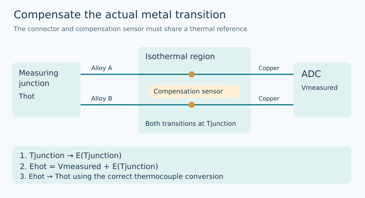
A thermocouple does not directly supply an absolute temperature reading. Its voltage depends on the measuring junction and the reference junction. In a gateway, the latter is normally associated with the transition from the thermocouple conductors to the measurement circuit’s ordinary conductors. A temperature sensor elsewhere on the board measures its own location, which is not necessarily a valid substitute.
Texas Instruments’ SBAA274A explains that the two thermocouple leads must be at the same known temperature for cold-junction compensation. Its suggested physical approaches include an isothermal block, appropriate copper fill, and protection from air currents. Those are implementation approaches, not a promise that a connector becomes isothermal merely because a temperature IC is nearby.
Begin the drawing at the cable, not at the ADC pins. Mark each change of conductor material, the two input terminals, and the compensation sensor. Then mark nearby heat sources. This review often exposes a disconnect between a schematic label such as “ambient temperature” and the actual quantity that the conversion needs.
Compensation is a voltage-domain operation
Let E(T) denote the selected thermocouple type’s voltage relative to a zero-degree reference. Under the usual isothermal reference-junction assumption, the measured signal is E(Thot) minus E(Tjunction). The calculation reconstructs E(Thot) by adding E(Tjunction) to the measured voltage, then applies the inverse conversion to obtain temperature.
Do not generally convert the measured voltage to a temperature and then add the compensation sensor’s temperature. Thermocouple response is nonlinear. SBAA274A explicitly describes the forward conversion, voltage addition, and inverse conversion sequence. Firmware should also use the correct thermocouple type and coefficient or table interval. A mathematically correct operation for the wrong alloy pair is still the wrong measurement.
A useful software-only check supplies a synthetic hot-junction temperature and a synthetic reference temperature, computes their voltage difference, and confirms that the compensation path reconstructs the original hot temperature. Use values across the supported ranges, including a reference temperature different from room temperature. This checks the conversion sequence without claiming to validate the physical connector.
A perfect compensation sensor can still be in the wrong place
Suppose the terminal block is at 35°C while a precisely calibrated board sensor reports 30°C. The software then adds the thermocouple-equivalent voltage for 30°C, not for 35°C. The reconstructed hot-junction voltage is too low for a thermocouple range where the relevant sensitivity is positive.
The resulting temperature error should not automatically be labeled exactly minus five degrees. For a small mismatch, the error is approximately the junction-temperature mismatch multiplied by the ratio of thermocouple sensitivities at the reference and hot junctions. That ratio changes with type and operating temperature. This is a local approximation, not a replacement for the nonlinear conversion.
More importantly, if the two terminal transitions are themselves at substantially different temperatures, one compensation temperature no longer describes the assumed reference boundary. Averaging two arbitrary board temperatures does not prove that the error has been corrected. The mechanical and thermal arrangement must support the model used by the calculation.
Separate electrical accuracy from thermal tracking
An electrical simulator remains useful: it can exercise the input range, polarity, conversion, and gain. Document whether it supplies a raw millivolt signal or simulates a thermocouple with its own compensation, and where its connection changes conductor material. Otherwise, two compensation systems can obscure what the fixture is actually testing.
For the thermal question, hold the measuring junction at a stable independently observed condition and change the gateway’s thermal state without intentionally changing that junction. Compare startup, sustained communications activity, and the intended enclosure airflow conditions. Observe the input terminal region and compensation sensor region independently where practicable. These are proposed engineering observations, not reported measurements from an Obeita product.
Look at time alignment as well as steady-state error. A board sensor that eventually reaches the terminal temperature may still track it too slowly during warmup. Record raw thermocouple voltage, compensation temperature, calculated temperature, and elapsed time together. If only the final compensated value is retained, thermal mismatch and conversion mistakes can look frustratingly similar.
Make the installation preserve the boundary
The installation drawing should identify the intended thermocouple type, permitted extension arrangement, connector mapping, and the location at which the instrument performs reference compensation. An undocumented conversion to ordinary copper in an intermediate junction box changes the physical problem. Do not assume that the gateway can compensate for a remote, unmeasured transition simply because its firmware has a cold-junction routine.
Likewise, a replacement enclosure, terminal block, or neighboring power module can alter the thermal relationship without changing a single register. Treat those changes as reasons to revisit thermal tracking. A useful acceptance record distinguishes electrical conversion accuracy from reference-junction agreement, and states the operating and warmup conditions under which each was evaluated.
The design goal is not merely a high-resolution thermocouple number. It is a defensible link between the metal transition, the temperature actually measured there, and the compensation voltage the software adds. Establishing that link prevents an apparently accurate board-temperature sensor from concealing the wrong reference junction.
Primary reference
Texas Instruments, A Basic Guide to Thermocouple Measurements, SBAA274A, March 2023 revision, sections 1.1 and 1.3–1.4. The physical review and diagnostic sequence above are engineering recommendations derived from the measurement model, not vendor-tested performance claims.