I2C Address Collisions: Decide Between a Mux, Address Strap and Separate Bus
Two devices with the same I2C address need separate visibility, a supported address change, or separate buses. Different software names do not separate electrically connected responders. Choose the topology first, then make branch selection and target access one owned operation.
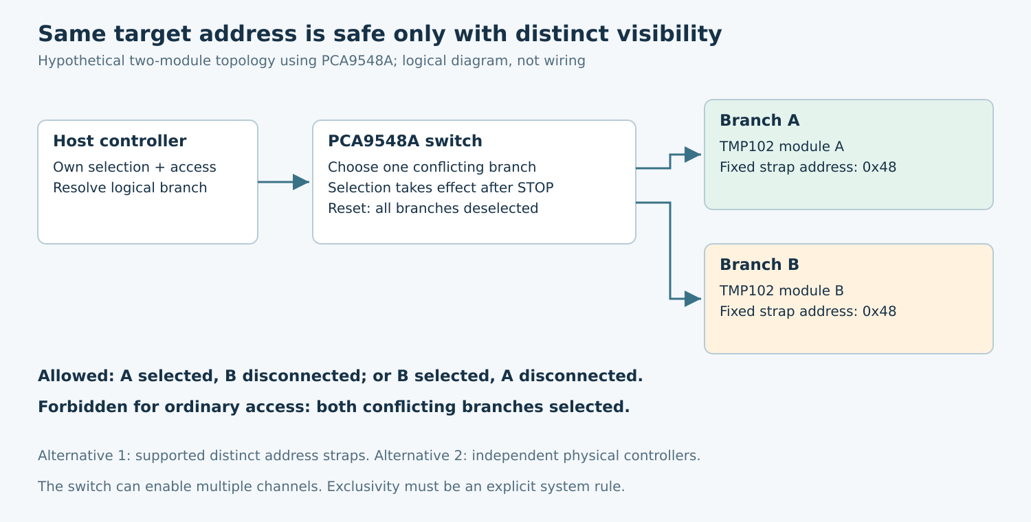
Applicability: this guide uses TI TMP102 address options from SBOS397I and NXP PCA9548A switch behavior from revision 5.1. Linux examples concern logical I2C buses and mux ownership. The drawing is a logical topology, not a pinout or an electrically qualified circuit.
1. Prove the collision rather than counting ACKs
Inventory the physical devices, their seven-bit addresses, strap settings, power domains, and every switch state that can connect them. Include the switch’s own upstream address and any fixed-address device already on the root bus. Two address values written in a device tree are not evidence that the physical parts use those values.
A scan showing one responding address does not prove that exactly one device responded. Two targets can both acknowledge; a write may reach both, and simultaneous read responses can produce a misleading value. Use documented identity or controlled behavior after isolating one target at a time. Do not use indiscriminate probing on equipment whose registers have side effects.
For a hypothetical assembly, consider two TMP102 modules whose address inputs are permanently tied to ground. Both use the same address. Their temperature readings may even be similar, hiding the collision. The task is to identify which physical module supplied each reading, not simply to make an ACK appear.
2. Prefer a supported address strap when it solves the real problem
The TMP102 datasheet provides four address choices through its address-input connection. Ground and supply select different documented addresses; the table also specifies SDA and SCL options. Use that exact table for the selected part rather than borrowing a strap convention from another sensor.
If the board exposes a safe strap change, distinct addresses can avoid an extra switch and its software state. Check assembly variants, boot behavior, and connector interchangeability. Mark the address choice in manufacturing records so replacing one module does not recreate the collision.
A programmable address can also work when the component supports it, but inspect its reset address and when the new value takes effect. If all devices boot to one address, the system still needs a way to select them individually during assignment. Address programming is not a solution until the startup sequence is unambiguous.
3. Use a switch with an explicit exclusivity policy
The PCA9548A datasheet describes independently selectable downstream channels and permits multiple channels to be enabled. It is therefore unsafe to assume that installing this part automatically creates one-of-eight exclusivity. Firmware must select only the intended conflicting branch at each target access.
For the hypothetical two-module assembly, connect each module to a different logical downstream branch and require exactly one selected branch when accessing their shared address. A branch mask enabling both recreates the collision. This remains true even if the two target objects have different names in the application.
The PCA9548A activates a newly selected channel after STOP. Its reset and power-on state deselect all channels. Those details belong in the selection protocol and boot tests. Do not replace the required switch-selection completion with a repeated START to the downstream target and assume the branch is already connected.
Check pull-ups, switch voltage behavior, on-resistance, and capacitance for every allowed topology. Enabling additional branches changes electrical loading as well as address visibility. The switch datasheet is necessary but cannot establish the limits of the populated board or its downstream components.
4. Consider separate controllers when independence matters
A separate physical I2C controller can isolate address space without a selector device. It may also provide cleaner failure containment and concurrent access. The costs include pins, routing, controller availability, and additional software configuration. Confirm that two advertised connectors actually reach independent controllers rather than one shared bus.
A switch is attractive when pin count is limited and sequential branch access is acceptable. Address straps are attractive when enough choices exist and the board can enforce them reliably. Separate buses are attractive when simultaneous traffic or fault containment is important. Compare these outcomes against requirements instead of ranking options only by component count.
Record how an unavailable or unpowered branch affects the rest of the system. Address isolation does not automatically provide power isolation. An unpowered device or inappropriate level translator can still interfere through its pins. Evaluate those paths with the actual schematic and component operating limits.
5. Give selection and access one software owner
The Linux I2C sysfs guide distinguishes physical controllers from logical buses behind mux channels. Resolve the logical path through its topology rather than assuming a bus number will remain constant after a configuration change.
Use the mux-aware kernel path when it owns the switch. The Linux topology documentation explains different mux locking arrangements and their constraints. A standalone userspace “select channel” write can race a driver transaction unless the complete ownership design explicitly prevents it.
The critical operation is select the intended path, perform the complete target transfer, then apply the declared idle policy. Serializing only the target transfer leaves a gap in which another client can change the path. Record branch identity with every result so consumers cannot accidentally exchange two physically distinct sensors.
6. Validate isolation with branch-specific evidence
- Cold boot: confirm the switch starts in its documented unselected state and software selects the intended branch before access.
- Single-branch access: apply a safe, controlled stimulus to only one module. Verify that only its logical reading follows that stimulus.
- Alternating traffic: repeatedly switch between branches under concurrent application requests. Check recorded branch identity and target data together.
- Forbidden mask: verify that software rejects a selection exposing both same-address devices. Do not intentionally create contention on operational equipment.
- Reset and missing branch: reset the switch or make one test branch unavailable. The next access must reselect correctly or report a clear failure without attributing another branch’s data to it.
Retain the address/topology inventory, selector ownership rule, observed switch state, and branch-specific results. No bus scans, strap changes, or hardware tests were performed for this article. The proposed procedure qualifies address visibility and identity; electrical margin and reset/power behavior still require board-specific validation.