Active-Low GPIOs: Keep Logical Assertion Separate from the Measured Pin Level
Choose one software meaning for assertion and let the GPIO descriptor map it to the required controller-pin level. In the Linux descriptor API, logical one means active; it does not always mean a measured high voltage. A second inversion in application code can silently undo the board description and reverse a reset or enable signal.
Applicability: this procedure uses Linux v6.12 GPIO descriptor consumers and generic device-tree GPIO conventions. The two board variants below are hypothetical logic relationships, not validated circuits. Voltage thresholds, pull resistors, power-off behavior, and external inverter selection require the actual component documentation.
1. Define the intended action before naming a voltage
Start with a sentence such as “asserting this signal holds the peripheral in reset.” Keep that action separate from the signal’s active-low marking, the host pad level, and any inverter between the pad and peripheral. Labels such as reset_n help communicate intent but do not configure software.
Create four columns: application action, descriptor logical value, controller-pad level, and target-pin level. Add a fifth column naming any intervening inversion. Fill the complete truth table from the board schematic and selected part’s documented assertion condition before editing a driver.
If the peripheral can program its own input polarity, record that setting too. A device-internal polarity choice and a board-level inverter are distinct configuration inputs. Changing one may require a new table; it should not trigger an unexplained Boolean negation elsewhere.
2. Apply the descriptor’s logical-value contract
The Linux v6.12 consumer documentation specifies that ordinary gpiod value accessors account for active-low configuration. For a push-pull active-low descriptor, logical one requests a low pad level and logical zero requests high. An active-high descriptor maps those values directly.
Raw accessors bypass the logical active-low interpretation. Mixing raw and logical calls on the same signal makes local reasoning harder: a literal one may have different meanings in adjacent functions. Prefer logical access throughout a device-independent consumer and reserve any necessary raw operation for an explicitly documented hardware-specific boundary.
Audit initialization flags as well as later writes. GPIOD_OUT_HIGH denotes an initially high logical value, so an active-low descriptor starts asserted at a low pad level. A misleading comment saying “start with pin high” can conceal a reset-state bug even when the code follows the API correctly.
3. Compare two hypothetical board variants
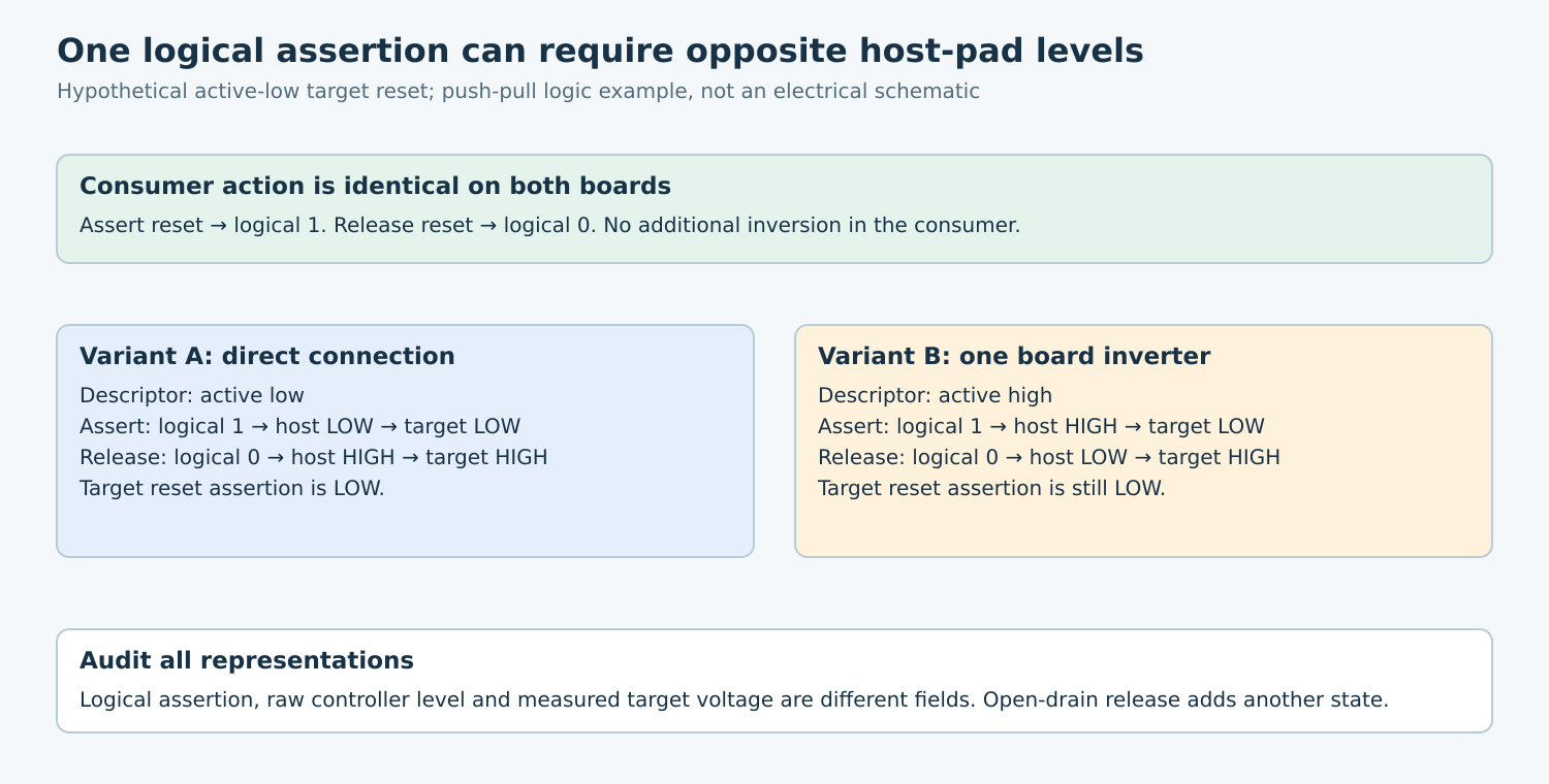
Suppose the target reset pin is active low. Variant A connects the host pad directly to that pin. Its descriptor is active low: asserting reset uses logical one, producing host low and target low. Releasing reset uses logical zero, producing high at both points.
Variant B inserts a logical inverter before the same active-low target pin. Its host-side descriptor is active high: asserting reset still uses logical one, but the host goes high and the target goes low. Releasing reset uses logical zero, making the host low and the target high.
The generic GPIO binding conventions explain why board-level inversion must be reflected at the GPIO-controller boundary. The consumer can express the same action on both variants while their pad voltages differ. Specific device bindings can impose additional conventions, so inspect the binding used by the actual driver.
If application code changes assert to a literal zero because the target is named reset_n, Variant A inverts twice: the descriptor maps that zero to an inactive high level. Correct the representation boundary rather than fixing one call site with another unexplained inversion.
4. Keep drive mode separate from logical polarity
An open-drain output can release the conductor instead of actively driving it high. The logical assertion mapping still matters, but a requested released state is not proof of a valid high voltage at the target. External bias, loading, another active driver, or partial power can determine the observed level.
Record drive mode alongside polarity. For each table entry distinguish “actively low,” “actively high,” and “released.” Avoid describing all three as simple Boolean voltage states. Use the selected hardware’s requirements to decide what measurement proves an inactive line.
Likewise, a successful software setter does not demonstrate target voltage or device response. The controller can be correctly programmed while pin multiplexing, a connector, or an unpowered translator interrupts the signal path. Measure at the target when the intended action depends on that point.
5. Audit every path that touches the signal
- Acquisition: verify the descriptor identity, board property, initial direction, and initial logical value.
- Normal operation: list logical and raw getters/setters and remove undocumented polarity conversions.
- Failure cleanup: verify that “safe” means the intended device action rather than an assumed voltage.
- Reset and resume: check that restored pin configuration preserves the same mapping.
- Diagnostics: label displayed values as logical assertion, raw controller level, or measured target voltage.
Do not dynamically toggle descriptor polarity merely to make a diagnostic value agree with a probe. That changes the interpretation for other users of the descriptor. Correct the board description or consumer contract through the normal reviewed configuration path.
For input lines, apply the same distinction when reading assertion state. A logical active result may correspond to a low pin. Do not invert it again just because the schematic uses an overbar. Handle returned errors before treating an integer as an asserted Boolean. The exact v6.12 gpiolib implementation returns a negative read error before applying active-low inversion; the consumer guide retains an older blanket statement that getters do not return errors.
6. Verify actions and observations together
On a safe development setup, exercise asserted and inactive states for each supported board variant. Record the logical request, controller state, target voltage or waveform, and device response. Use permitted operating conditions and avoid switching a consequential output without a controlled fixture.
Include startup and cleanup observations, because a steady-state truth table does not prove glitch-free transitions. If the target enters reset at the wrong time but later levels are correct, investigate direction/enable and pinmux handover separately from logical inversion.
No GPIO was driven for this article. The deliverable is a board-specific truth table and an accessor audit that lets another engineer predict the target action from a logical request. A reusable driver should express assertion consistently; the verified descriptor and hardware path determine the voltage needed to make that action happen.