UART Hardware Flow Control: Prove the Peer Stops Before the Receive Buffer Overflows
Assert backpressure while enough receive capacity remains for every character that can still arrive. Prove that margin by measuring the stop request at the receiver, its arrival at the peer, and the final received character. RTS/CTS is not an instantaneous stop, and a UART FIFO’s automatic protection does not automatically protect a later software queue.
Applicability: the concrete UART is NXP SC16IS750, using the SC16IS740/750/760 datasheet revision 7.1, February 2025. A hypothetical direct link between two such UARTs provides the example. USB bridges, isolators, other peers, and software-controlled RTS require their own timing evidence.
1. Identify which buffer controls RTS
Draw the receive path from wire to shift register, UART FIFO, bus driver, software ring, and application. Mark the buffer occupancy that actually changes RTS. A register setting named hardware flow control is not proof that the application queue participates in the decision.
The SC16IS750 datasheet describes a 64-byte receive FIFO and independently enabled automatic RTS and CTS. Automatic RTS uses configured halt and resume levels associated with FIFO occupancy. The receiver’s RTS connects to the sender’s CTS for this flow-control relationship.
If software continuously drains the hardware FIFO into a full application ring, automatic RTS may remain permissive while data are lost later. Define a separate software-capacity policy, such as stopping the drain safely or controlling admission through a supported mechanism. Do not solve one overflow by silently moving it downstream.
2. Verify polarity and the peer’s stopping rule
For the selected part, CTS is active low. Its automatic transmitter checks CTS before the next byte; the datasheet describes the timing condition relative to the current character’s final stop bit. A change arriving too late can permit an additional character. The current character is not chopped in half to satisfy the stop request.
Capture both the local RTS pin and the peer CTS pin where practical. Board inversion, level translation, isolation, and wiring can change the relationship between a software logical state and the actual electrical permission to transmit. Use the selected components’ limits and appropriate probes; this article specifies no universal propagation allowance.
Keep hardware flow control separate from RS-485 direction control. The same pin name may be repurposed by another mode. Verify pin multiplexing and mode configuration before interpreting a waveform as a backpressure request.
3. Build a conservative headroom budget
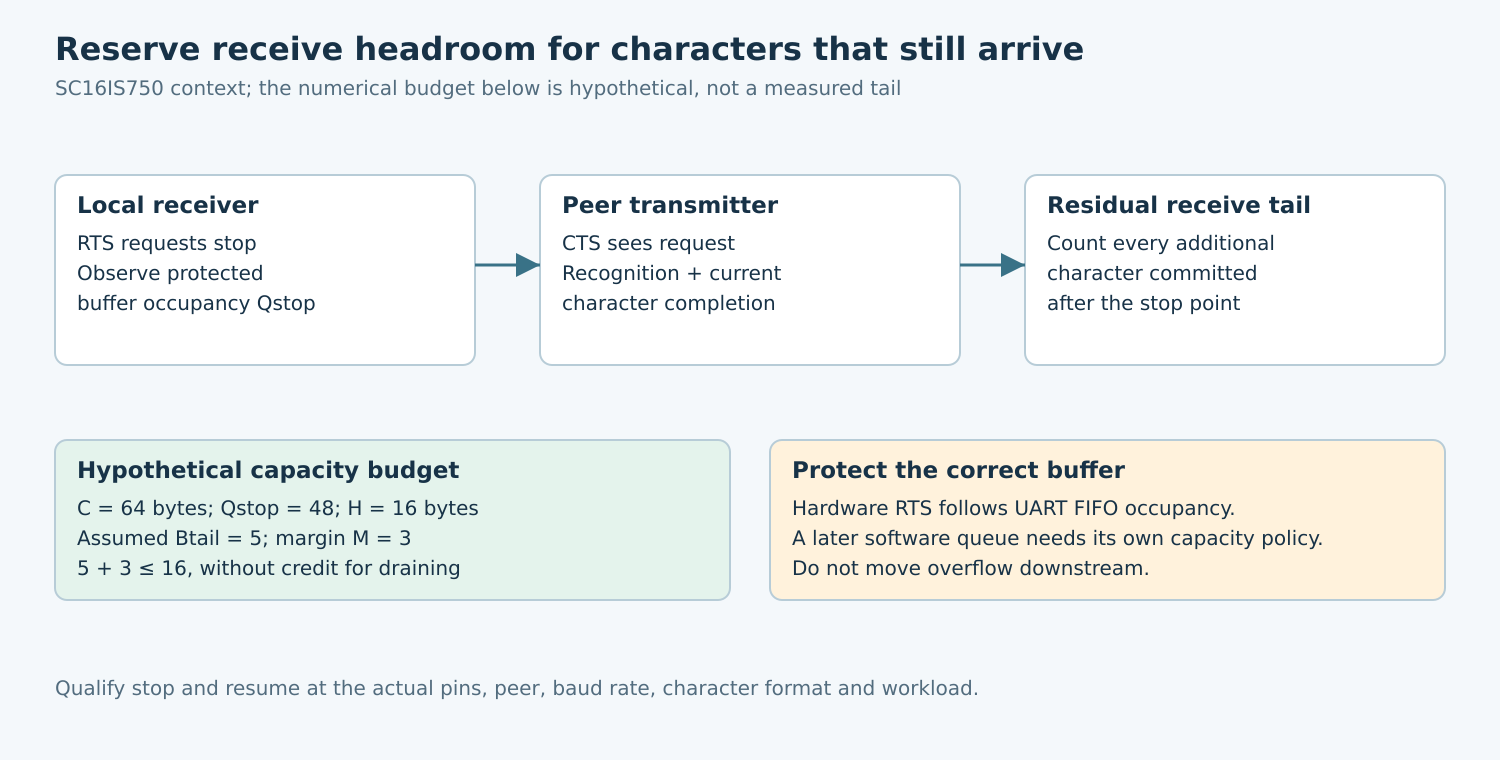
Let C be the protected buffer’s usable capacity and Qstop its occupancy when the stop request takes effect at the chosen local observation point. Available headroom is H = C − Qstop. Let Btail be the maximum number of additional characters committed to that buffer after this point, and M a deliberately reserved margin.
A conservative acceptance condition is Btail + M ≤ H, without crediting any concurrent drain. This separates storage units from time units. If a timing model is used to estimate Btail, include character format, an already-started character, the peer’s recognition rule, and any bridge buffering. Do not count the same in-flight character twice.
In a hypothetical budget, a 64-byte FIFO stops at occupancy 48, leaving sixteen bytes. An assumed tail allowance of five bytes plus a margin of three fits within that space. These numbers illustrate the calculation; five is not a measured or specified SC16IS750 tail, and the example does not qualify a real link.
If RTS is controlled by software, Qstop can exceed the threshold that woke the task. Include occupancy growth during interrupt delivery, scheduling, register access, and output propagation. Measuring only the final GPIO transition omits the time already spent reaching it.
4. Measure stop-to-last-character behavior
- Use a known stream: send identifiable sequence bytes or framed counters from an approved peer, with a way to detect loss and duplication.
- Raise occupancy deliberately: slow or pause the protected consumer on a test setup while retaining a safe restoration path.
- Capture control and data: mark local stop request, peer CTS transition, character boundaries, and the last character received after stopping.
- Count the tail: include any character already in progress that reaches the protected buffer after the stop point.
- Repeat boundary phases: move the stop edge relative to character transmission and repeat across supported baud rates and relevant load.
Log the configured halt/resume thresholds and read back the active configuration. The Linux v6.12 low-level serial API defines a throttle notification for line-discipline input pressure separately from modem-line control. An API request still needs a review of the bound driver’s hardware path; it does not establish a measured response time.
5. Test restart and sustained backpressure
Choose a resume threshold below the halt threshold so the receiver gains useful capacity before allowing more traffic. The selected UART’s TCR provides separate halt and resume controls; confirm its encoding and permitted values in the datasheet before programming them.
Hold the stopped state long enough to expose peer queues and timeout policies. Verify that the peer truly pauses rather than dropping data, resetting the connection, or treating CTS as advisory. If the protocol has a response deadline, include the permitted backpressure interval in that contract.
Then resume and check ordering, duplicates, framing, and FIFO or software-overrun indicators. A clean first burst is not enough if repeated stop/resume cycles eventually lose a character. Exercise the highest sustained offered load the product is expected to handle.
6. Interpret failures at the correct boundary
Overflow before RTS changes points to a late local threshold or control path. Bytes continuing despite a correctly observed peer CTS stop state point to peer configuration, recognition latency, or bridge behavior. Loss with no hardware FIFO overflow can originate in the driver or application queue.
Keep those observations separate. Increasing the software ring may hide a delayed stop without fixing it; lowering baud may reduce pressure while leaving the same unbounded path. The useful repair demonstrates a bounded tail and adequate headroom at every protected buffer.
No UART measurements were performed for this article. The release evidence should include the exact UART and peer, active mode, polarity trace, occupancy definition, observed tail under stated conditions, and justified margin. A datasheet’s automatic-flow-control feature is the starting contract, not a substitute for the product’s end-to-end overflow proof.