Brownout Reboots During Radio Bursts: Capture Supply and Reset Evidence on One Timeline
A reboot near radio transmission is not enough to diagnose brownout. Capture the voltage at the MCU supply, a trustworthy load-activity marker, and evidence of a new boot on one timeline. Then interpret the earliest reset status using the selected device’s rules. A stable bench-supply display and an empty crash log cannot exclude a short local supply collapse.
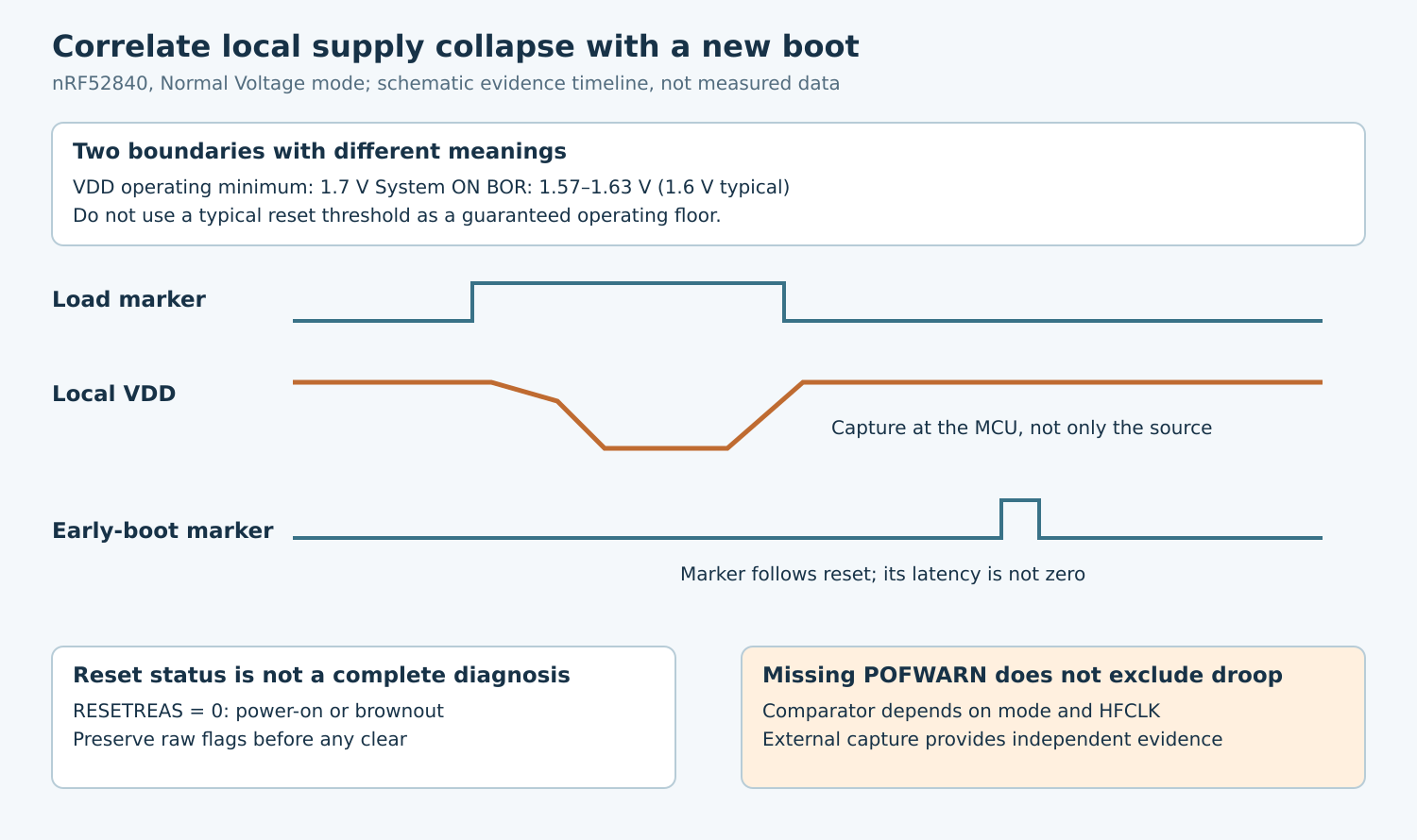
Applicability: the concrete MCU is nRF52840 in Normal Voltage mode, using Product Specification v1.8. The electrical limits below belong to that part and operating mode. The proposed capture and comparisons have not been performed; the schematic timeline illustrates evidence ordering, not a measured radio waveform.
1. Separate the operating limit from the reset threshold
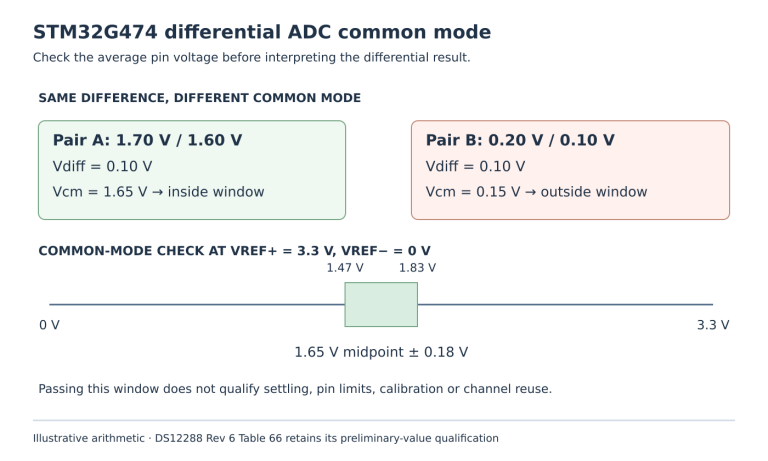
The nRF52840 recommended operating conditions specify VDD from 1.7 to 3.6 V and at least 1.75 V during power-on reset. By contrast, Product Specification v1.8 section 5.3.8.4 gives the System ON brownout range on VDD as 1.57–1.63 V, with 1.6 V typical. These are different boundaries.
A waveform that falls below the operating minimum but stays above a typical brownout value is not evidence of valid operation. Likewise, one nominal reset threshold cannot describe every part and condition. Use the specified range and the actual board’s supply mode, temperature envelope, and additional peripheral limits.
Do not deliberately operate production equipment outside its ratings to obtain a dramatic failure. Restrict fault reproduction to a recoverable development fixture under an approved hardware test plan, with consequential outputs inhibited and an independent recovery route.
2. Capture the voltage where the failure can occur
Probe the MCU’s local VDD relative to its local ground using an appropriate low-inductance connection. If possible, observe the regulator output or source separately. A voltage measured at the supply terminals may miss cable, connector, switch, or PCB impedance between the source and the MCU.
Choose probe bandwidth, sample rate, acquisition length, and trigger settings for the suspected event. Preserve pre-trigger history and avoid an acquisition mode that only retains a misleading average. Document probe loading and grounding; a long ground connection can turn switching activity into an apparent voltage disturbance.
Retain a load-current observation when the setup can provide one without disrupting the DUT. Otherwise use a documented radio event or firmware marker and label its timing relationship. A marker before a transmit request does not establish the exact instant or amplitude of the RF power-stage current.
3. Add reboot evidence without assuming a reset-pin output
Use a distinctive early-boot marker and a boot sequence identifier, or another documented platform observation. Record the latency between reset release and that marker as an uncertainty rather than treating it as the exact reset edge.
If an external reset signal is captured, verify what that signal represents on the chosen board. Do not assume that an MCU’s reset input automatically exposes every internal reset source as an output pulse. A flat reset-input trace can coexist with an internal reset.
For a hypothetical failure, the useful ordering is load activity, local VDD deterioration, loss of application progress, and a new boot after recovery. That ordering supports the supply hypothesis. It does not yet exclude a software fault that changed the load or a separate reset source occurring at the same time.
4. Preserve the nRF52840 reset register correctly
The POWER chapter states that RESETREAS accumulates flags until cleared and uses write-one-to-clear fields. With no reset sources flagged, the documented interpretation is power-on reset or brownout reset. Zero therefore cannot distinguish those two causes by itself.
Capture the raw value at the earliest supported boot stage before another component clears it. If a bootloader owns that read, pass the original value and boot identity to the application. Record when flags are cleared so an old watchdog indication is not mistaken for the current failure.
Correlate zero status with the external capture and power history. A clean cold start can legitimately produce the same ambiguous classification as a brownout. Conversely, a retained flag from another reset does not replace examination of the supply waveform and boot-chain handling.
5. Treat power-fail warning as conditional evidence
The same POWER chapter documents an optional power-fail comparator and POFWARN event. It is inactive in System OFF and in System ON when HFCLK is not running. Its warning path is therefore not a universal recorder of every low-voltage excursion.
Check the actual comparator configuration and clock conditions before interpreting a missing warning. If the voltage falls too quickly for software to respond, a correct event configuration still does not guarantee a durable log entry. Use external capture as the independent observation rather than making the diagnosis depend on an emergency flash write.
A warning can also be associated with enabling or reconfiguring the comparator when voltage is already below its selected threshold. Preserve configuration changes in the record. Do not equate every warning with a newly occurring radio-induced droop.
6. Change one cause candidate at a time
Repeat the same firmware workload with a known suitable source and documented wiring, then compare the intended battery or supply path. Keep radio settings and application activity fixed. If the failure follows one power path, inspect that path’s dynamic behavior rather than immediately changing scheduler priorities.
Next vary one supported load condition, such as a documented radio operating setting or simultaneous peripheral activity. Compare complete waveforms, not merely reboot counts. An improvement after shortening supply leads supports an impedance-related investigation but is not a substitute for validating the final product wiring.
Review decoupling, regulator transient response, source current limiting, connectors, and layout against their actual component documentation. Do not prescribe one capacitor value or current limit for every board. Added capacitance can alter startup behavior, so include power-on and restart tests after any hardware change.
7. Close with a bounded causal statement
Keep observed voltage extrema, acquisition uncertainty, raw reset status, boot markers, firmware identity, and functional results together. State whether the evidence establishes a supply-limit violation, is consistent with brownout, or proves a different reset mechanism. Do not upgrade an ambiguous zero reset value into a definitive diagnosis.
Acceptance requires both an adequate supply envelope during the real workload and reliable recovery under the supported conditions. Recheck with production-equivalent debug and measurement connections. A board that stops rebooting after a bench change still needs evidence that the shipped power path remains within its documented operating limits.