Startup Inrush and Current-Limited Supplies: Find Why a Board Boots Only on the Bench
A board that boots from a generous bench supply but repeatedly restarts from its intended source may be demanding more startup current than that source can deliver while maintaining voltage. Capture the input ramp, downstream rail, current-limit state, and first boot activity. Separate charging the board’s capacitance from powering the load that starts while that capacitance is still charging.
Applicability: this procedure addresses low-voltage embedded-board startup. Texas Instruments TPS22918, datasheet SLVSD76C revised July 2017, illustrates adjustable load-switch rise time. The numerical budget is an idealized hypothetical example, not a validated TPS22918 design or measured supply response.
1. Reproduce a true cold start
Record the supply model, output mode, voltage setting, current limit, protection settings, lead arrangement, board revision, and firmware. Verify safe discharge through the board’s documented path before a cold-start test. Do not short capacitors or defeat protection to accelerate the procedure.
Compare a genuinely discharged start with a warm restart. A partially charged input or downstream capacitor can make the second attempt substantially easier. If an engineer attaches the bench supply after a USB cable has already energized part of the board, the apparent success may not represent the product’s startup sequence.
Map every rail and its enabling condition. Identify which loads are held in reset, which begin autonomously, and which are enabled by firmware. An application delay cannot prevent current drawn before the CPU starts executing it.
2. Identify what the source does at its limit
Keysight’s description of DC-source priority modes explains that a voltage-priority source no longer holds its programmed voltage after reaching the relevant current limit. The actual instrument’s mode and protection configuration determine what follows.
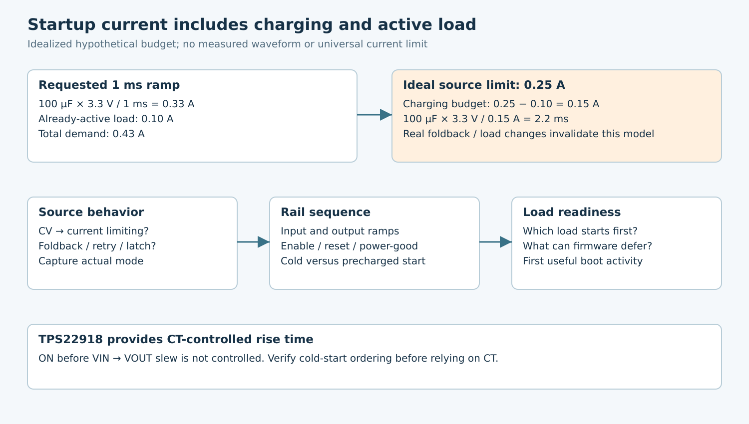
Distinguish continued constant-current operation from foldback, timed retry, or latched output shutdown using the selected source documentation and observations. Do not model all current-limited sources as an ideal constant-current generator. Preserve the protection indication and its timing alongside the analog capture.
Capture source voltage and board input voltage separately when practical. A source may regulate correctly at its terminals while cable or connector resistance causes a local deficit. Conversely, a repeated source shutdown can explain board resets even when the average displayed current looks modest.
3. Budget capacitor charging and active load separately
For a constant capacitance and approximately linear voltage ramp, capacitor current is C multiplied by dV/dt. The source also supplies whatever the downstream circuitry consumes during that ramp. Use effective capacitance under bias and tolerance rather than assuming the printed capacitor value is exact.
In a hypothetical model, charging 100 µF from 0 to 3.3 V in 1 ms requires 0.33 A for the capacitor alone. If an assumed constant 0.10 A load is already active, total demand is 0.43 A. An ideal source limited to 0.25 A cannot sustain that specified ramp and load simultaneously.
Under the same simplified assumptions, only 0.15 A remains for charging. The corresponding lower-bound charging time is C × ΔV divided by 0.15 A, or 2.2 ms. This is not a prediction for a real converter: its load may vary with voltage, current limiting may fold back, and startup control may repeatedly reset.
The useful question is therefore not just “is the steady current below the limit?” Ask whether the rail can reach the required startup voltage before the source or load changes state. A repeated rise-and-collapse pattern needs its state transitions explained.
4. Use slew control within the component contract
The TPS22918 datasheet provides a CT pin for configuring output rise time and discusses capacitive inrush in section 9.2.2.5. Section 8.3.3 describes the approximate CT-to-slew relationship. Use the documented conditions and switching tables when selecting a starting design value.
Section 10 adds an essential sequencing condition: if ON is powered before VIN, the output slew rate is not controlled. A larger CT capacitor cannot establish the intended ramp in that case. Capture VIN and ON ordering during true cold startup, and distinguish it from enabling the switch after VIN is already valid.
Do not mistake the device’s maximum continuous-current rating for a programmed current-limit threshold. Controlled rise time can reduce the capacitive part of startup demand, but it cannot make an excessive steady load acceptable. A slow ramp also has to satisfy the downstream devices’ supply-ramp and reset requirements.
Distinguish the datasheet’s defined rise-time interval from a full zero-to-final-voltage interval when doing calculations. Do not insert a 10–90% timing value into a full-swing equation without adjusting the voltage interval. Independently check units and arithmetic rather than copying a worked example blindly.
5. Capture the state transition that prevents boot
Observe the load-switch input and output, its enable signal, the relevant reset or power-good indication, and a bounded early-boot marker. Choose measurement bandwidth and record length to cover both the initial edge and any repeated retry interval. For TPS22918, compare the actual cold-start ON/VIN sequence with the intended VIN-valid-before-ON sequence; do not infer CT-controlled behavior from the latter alone.
If the source remains stable but the downstream rail collapses after a load enables, investigate downstream startup demand and sequencing. If the input collapses first with a current-limit indication, investigate source capability and its protection behavior. If both rails are valid but reset stays asserted, follow the supervisor or enable contract instead.
Mark software timestamps as delayed observations. A UART message printed after boot cannot establish the exact moment a rail crossed its startup threshold. Use electrical observations for that boundary and preserve their uncertainty.
6. Compare remedies without hiding the cause
Propose one change at a time: a supported slower slew, deferred activation of an optional load, corrected wiring, or a source whose documented dynamic capability suits the product. Compare both cold and warm starts after each change.
Raise a bench current limit only after checking the board, switch, connectors, wiring, and source ratings. A higher limit can help discriminate an inrush hypothesis, but it can also conceal a fault or invalidate protection. Do not transfer the resulting setting into a production requirement without a justified current and thermal budget.
Similarly, additional capacitance may help a later burst while making startup harder. Re-evaluate charging demand, discharge behavior, restart interval, and component stress together. A local improvement in one waveform is not a complete power-sequence qualification.
7. Define a repeatable startup envelope
Retain the waveform set, source mode, startup capacitance estimate, load sequence, and exact component documentation. Test the supported supply and temperature conditions and the required off-time range. Record failed attempts as well as successful ones.
Accept the design when the intended source reaches and maintains the required rails, reset and enable sequencing is valid, and the application starts reproducibly without relying on residual charge. The calculation narrows the experiment; actual startup traces and component limits determine whether the final implementation is suitable.