Pogo-Pin Contact Failures: Separate Fixture Connection Errors from Product Defects
Classify a suspected pogo-pin failure by tracing the complete fixture contact path and changing one controlled factor at a time. A pass after reseating shows that the outcome depends on the changed condition; it does not establish that the product was good, that the pin was bad or that the original failure may be discarded.
This is a proposed bench diagnosis, using Harwin P70-6000045R’s published geometry as one concrete component example and NASA SP-2016-6105 Rev2 for verification evidence. No fixture was measured or unit retested. Mechanical forces, permitted electrical stimulus and acceptance thresholds must come from the actual fixture and product design.
Draw the measurement path before touching the clamp
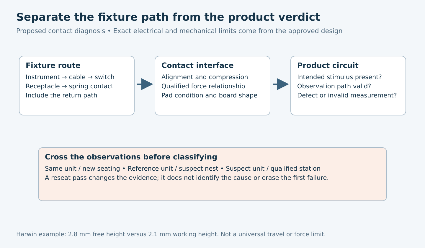
Follow the signal from instrument connector through cable, switching route, probe receptacle, spring contact, board pad and product circuit. Include the return path. A good signal contact with a poor ground contact can corrupt several apparently unrelated tests.
Assign identities to the fixture, nest, probe location and cable assembly. Record the unit, test stage, raw observation and clamp state at the first failure. An unexplained low analog reading, failed identification and unstable supply current may share a contact cause, but that relationship is a hypothesis until the paths are examined.
Do not start by adjusting firmware thresholds. First establish whether the intended stimulus reached the intended circuit and whether the observation returned through a valid path. A software tolerance change can conceal a mechanical defect while allowing genuinely defective products to pass.
Separate compression from force
The Harwin P70-6000045R product page identifies a 2.8 mm free height and 2.1 mm working height. Their 0.7 mm difference illustrates that free height and working position are distinct. It is not a universal travel recommendation for pogo pins, and it does not provide an allowable clamp force for a complete fixture.
Use the exact probe specification and approved drawing to establish the qualified compression interval and force behavior. Include board thickness, pad height, nest tolerance, clamp deflection and probe wear. A fixture may close against its stop while a bowed board leaves one contact under-compressed.
Inspect alignment and physical condition without applying power where the procedure requires isolation. Look for a missed pad, stuck plunger, damaged receptacle, contamination or visible board damage. Follow the component and process owner’s cleaning instructions; arbitrary abrasion or solvent can alter plating or contaminate the assembly.
If force is measured, record where and how. Total clamp force is not necessarily the force on a particular pin. Increasing the clamp load until the test passes is an uncontrolled intervention that can damage the board or change another contact.
Check continuity with an electrically reviewed method
De-energize and isolate the relevant path before a resistance or continuity check, following the fixture’s safe procedure. Confirm the instrument’s test voltage and current are compatible with connected circuitry. Do not inject an ohmmeter stimulus into a powered or unreviewed product path.
Measure sections where accessible: cable-to-receptacle, probe-to-pad and return path. Where low resistance matters, use the approved measurement arrangement and account for lead/contact contributions. A continuity buzzer is a coarse observation, not proof that the path meets its load-dependent voltage-drop requirement.
Conversely, a parallel circuit path can make an open intended contact appear continuous. Compare the measurement topology with the schematic. A standalone loopback artifact can help isolate the fixture, but it must exercise the relevant contact geometry and cannot automatically clear the product-side pad.
Use a controlled diagnostic matrix
| Controlled observation | What it helps distinguish | Important limitation |
|---|---|---|
| Original seating, repeated acquisition without handling. | Time-dependent instability versus a one-time reading. | The repeat can warm or condition the product. |
| Same unit, approved reseat, unchanged software and range. | Sensitivity to contact/alignment or handling. | Reseating changes several physical conditions. |
| Qualified reference unit in the suspect nest. | Whether the failure follows a fixture path. | The reference may have different pad wear or geometry. |
| Suspect unit on an independently qualified station. | Whether the symptom follows the unit. | Station setup and uncertainty must be comparable. |
| Approved continuity/compression checks at the suspect contact. | Direct evidence about the physical path. | A static check may miss a dynamic or loaded defect. |
Preserve the original failure and create a new observation for each intervention. Record which cable, nest, unit or clamp setting changed. Swapping the cable and unit together may recover the test but loses the ability to localize the cause.
Interpret crossed outcomes cautiously
In a hypothetical investigation, two units fail the same channel on station A and pass on qualified station B. The evidence points toward a station-specific path, but a shared setup difference still needs exclusion. Inspect that route before declaring both units good.
If only one unit fails on both stations, inspect its pad, assembly and circuit. If it passes only when pressed differently, the unit may have a real mechanical defect rather than an innocent fixture mismatch. A fixture should not compensate silently for an out-of-spec product.
If the failure appears only under load or during a transition, a static resistance check is insufficient. Plan a suitable bounded waveform or voltage-drop observation using approved probes and limits. No universal resistance threshold or current pulse is supplied here because the product’s circuitry determines what is safe and meaningful.
Close the diagnosis with a classified result
The NASA handbook’s verification guidance distinguishes product discrepancies from inadequate verification conditions and records configuration, discrepancies and corrective actions. Applied here, the station result should identify product failure, invalid measurement due to demonstrated fixture fault, or unresolved cause. “Passed on retry” is not a substitute for that classification.
After a confirmed fixture repair, qualify the repaired path and review earlier results that may have relied on it. After product rework, retain the original failure and run the approved affected-function tests. These are different change scopes and should not share an automatic blanket release rule.
The deliverable is the path drawing, continuity/compression evidence, controlled comparison matrix and explicit disposition. It should explain why a result can be trusted, which alternative causes remain open and what physical qualification is still required.